Gear chamfering device

A technology of chamfering device and gear, applied in the direction of gear tooth manufacturing device, belt/chain/gear, gear tooth, etc., can solve the problems of pollution, dust can not be effectively collected, easy to spread and hurt people

Inactive Publication Date: 2018-05-08
重庆厚朴开物科技有限公司
View PDF4 Cites 3 Cited by
  • Summary
  • Abstract
  • Description
  • Claims
  • Application Information

AI Technical Summary

Problems solved by technology

When chamfering the grinding wheel, it is necessary to ensure that the grinding wheel is in contact with the gear, and this will easily cause the gear to interfere with the grinding wheel when it is placed on the tooling, affecting the

Method used


Image

  • Gear chamfering device
  • Gear chamfering device

Examples


Embodiment Construction

[0015] The present invention will be described in further detail below by means of specific embodiments:

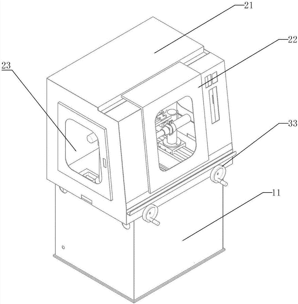
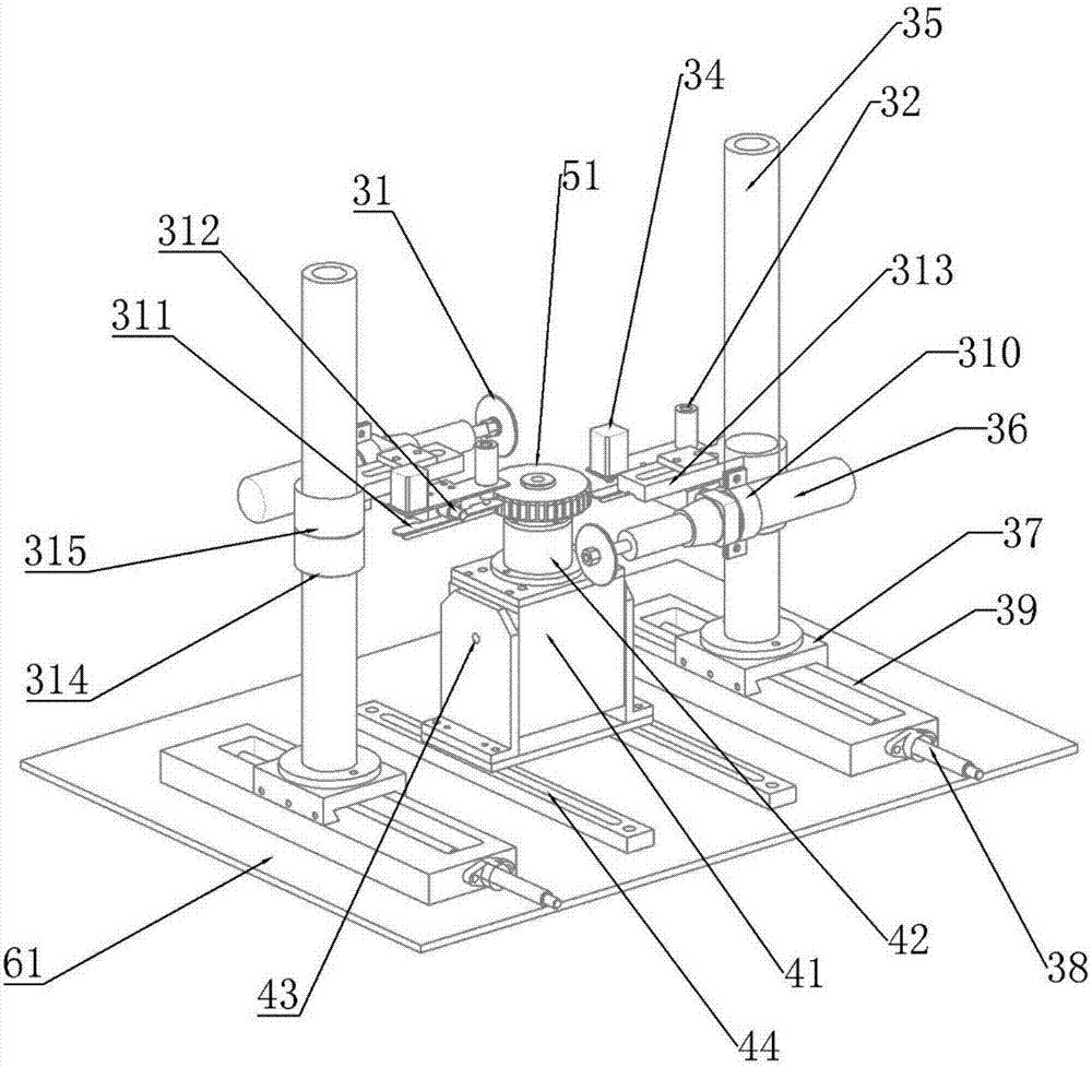
[0016] The reference numerals in the accompanying drawings of the description include: vacuum bin 11, housing 21, door 22, transparent observation window 23, grinding wheel sheet 31, spring 32, hand wheel 33, cylinder 34, threaded column 35, electric grinder 36, Slider 37, screw mandrel 38, slide rail 39, clamp 310, balance plate 311, rotating shaft 312, fixed plate 313, threaded part 314, rotating arm 315, main chassis 41, tooling 42, pin shaft 43, T-shaped slot 44 , gear 51, connecting plate 61.

[0017] The embodiment is basically as attached figure 1 and figure 2 Shown: a gear chamfering device, including a housing 21, a chamfering structure and a dust removal structure, the side wall of the housing 21 is provided with a door 22, and the side of the housing 21 is provided with a transparent observation window 23, which can pass through the transparent observation w...


PUM


Abstract

The invention belongs to the field of gear or rack manufacturing devices, and particularly discloses a gear chamfering device. The gear chamfering device comprises a shell, a chamfering structure anda dedusting structure. A door is arranged on the side wall of the shell. The shell is located at the upper end of the dedusting structure and communicates with the dedusting structure. A connecting plate is arranged at the lower end of the shell and provided with a plurality of through holes. The chamfering structure is located in the shell and comprises a clamping part and a polishing part. The dedusting structure comprises a dust bin. A dust collector is arranged in the dust bin and communicates with the through holes. By adoption of the gear chamfering device, a gear can be fixedly conveniently, and dust diffusion can be effectively prevented.

Description

technical field [0001] The invention relates to the field of gear or rack manufacturing devices, in particular to a gear chamfering device. Background technique [0002] A gear is a mechanical element with gear teeth on the rim that continuously meshes to transmit motion and power. At present, for gears that need to slide or shift gears in use, chamfering needs to be processed, and the chamfering of gears is generally processed by gear chamfering machines. In the processing process of the existing gear chamfering machine, the gear needs to be fixed and clamped by the tooling first, and then the gear is chamfered by the grinding wheel. When chamfering the grinding wheel, it is necessary to ensure that the grinding wheel is in contact with the gear, and this will easily cause the gear to interfere with the grinding wheel when it is placed on the tooling, affecting the fixing and clamping of the gear. Moreover, the dust generated in the existing gear chamfering process cannot...

Claims


Application Information

Patent Timeline
IPC IPC(8): B23F19/12B23F23/06
CPCB23F19/12B23F23/06
Inventor 李华
Owner 重庆厚朴开物科技有限公司
Why Eureka
Try Eureka