Eureka AIR delivers breakthrough ideas for toughest innovation challenges, trusted by R&D personnel around the world.

Shaft end jack

A shaft end and sheath technology, which is applied in the field of shaft end sheaths, can solve problems such as easy damage, damaged shaft ends, and affecting accuracy, and achieves the effect of convenient and reliable use and simple structure

Pending Publication Date: 2018-05-08
SUZHOU TINGYIHUA AUTOMATION EQUIP CO LTD
View PDF0 Cites 1 Cited by
  • Summary
  • Abstract
  • Description
  • Claims
  • Application Information

AI Technical Summary

Problems solved by technology

[0002] It is often necessary to install ring parts such as bearings and oil seals on the shaft. Some shaft ends are provided with threads. At this time, when installing or removing bearings or oil seals, the threads are easy to be damaged and the shaft is scrapped; For shafts with high precision requirements, friction is likely to occur during installation, which will damage the shaft end and affect the accuracy; moreover, when inserting the oil seal at the shaft end, sometimes improper operation will squeeze and damage the oil seal

Method used


Image

  • Shaft end jack
  • Shaft end jack

Examples


Embodiment Construction

[0013] The technical solution of the present invention will be described in further non-limiting detail below in combination with preferred embodiments and accompanying drawings.

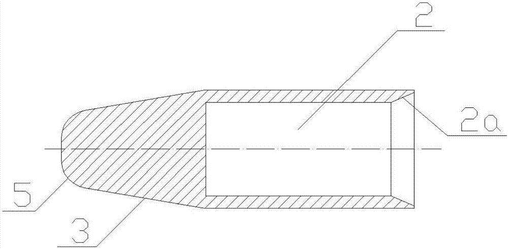
[0014] like figure 1 As shown, the shaft end sheath corresponding to a preferred embodiment of the present invention has a cylindrical shape as a whole, and an accommodation hole 2 for accommodating the shaft end 1 is opened in the center of one end, and a tapered surface 3 is provided at the other end, and the tapered surface 3 The transition to the end face 4 of this end is via a rounded corner 5 . The diameter of the accommodation hole 2 is slightly larger than the diameter of the shaft end 1, and a chamfer 2a is provided at the entrance to facilitate the entry of the shaft end 1. The depth of the accommodation hole 2 is preferably slightly greater than the length of the shaft end 1.

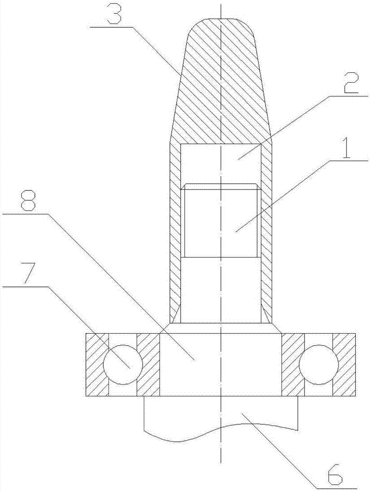
[0015] like figure 2 As shown, the shaft 6 includes a threaded shaft end 1 and a shaft portion 8 on which the...


PUM


Abstract

The invention discloses a shaft end jack. A shaft portion (8) connected with a shaft end (1) is arranged on a shaft (6). A bearing (7) is mounted on the shaft portion (8). A containing hole (2) for containing the shaft end (1) is formed in one end of the shaft end jack. The outer diameter of the shaft end jack is smaller than the inner diameter of the bearing (7). By using the shaft end jack capable of being arranged at the shaft end in a sleeving manner, the damage to the shaft end is avoided when annular parts such as a bearing and an oil seal are mounted on the shaft, and the shaft end jackis simple in structure and convenient and reliable to use.

Description

technical field [0001] The invention relates to a shaft end sheath. Background technique [0002] It is often necessary to install ring parts such as bearings and oil seals on the shaft. Some shaft ends are provided with threads. At this time, when installing or removing bearings or oil seals, the threads are easy to be damaged and the shaft is scrapped; For shafts with high precision requirements, friction is likely to occur during installation, which will damage the shaft end and affect the accuracy; moreover, when inserting the oil seal at the shaft end, sometimes improper operation will squeeze and damage the oil seal. Contents of the invention [0003] The object of the present invention is to address the above-mentioned defects in the prior art, and provide a shaft end sheath, so that the shaft end will not be damaged when disassembling and installing ring parts such as bearings and oil seals installed on the shaft. [0004] In order to achieve the purpose of the ab...

Claims


Application Information

Patent Timeline
IPC IPC(8): B65D59/00
CPCB65D59/00
Inventor 杨琦
Owner SUZHOU TINGYIHUA AUTOMATION EQUIP CO LTD
Why Eureka
Eureka Blog
Learn More