Suspended type monorail transit track beam

A technology for monorail traffic and track beams, applied in the field of rail traffic, can solve problems such as poor comfort and poor vibration damping performance, and achieve the effects of reducing vibration level, improving ride comfort, and reducing wheel-rail dynamic interaction.

Active Publication Date: 2018-05-08
SOUTHWEST JIAOTONG UNIV
View PDF30 Cites 8 Cited by
  • Summary
  • Abstract
  • Description
  • Claims
  • Application Information

AI Technical Summary

Problems solved by technology

[0007] The object of the present invention is to provide a suspended monorail traffic track beam to solve the problems of poor vibration damping performance of the existing suspended monorail traffic track beam and poor comfort during train operation. Vibration-absorbing performance of the beam to improve the comfort of train operation

Method used


Image

  • Suspended type monorail transit track beam
  • Suspended type monorail transit track beam
  • Suspended type monorail transit track beam

Examples


Embodiment 1

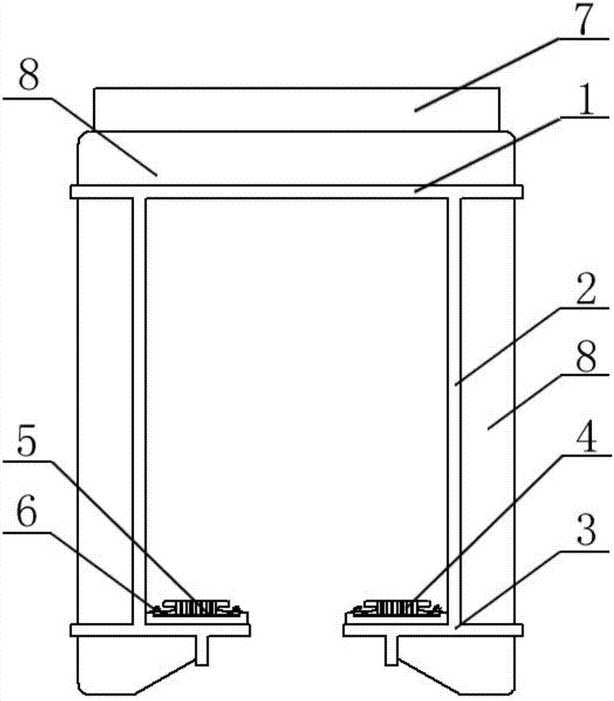
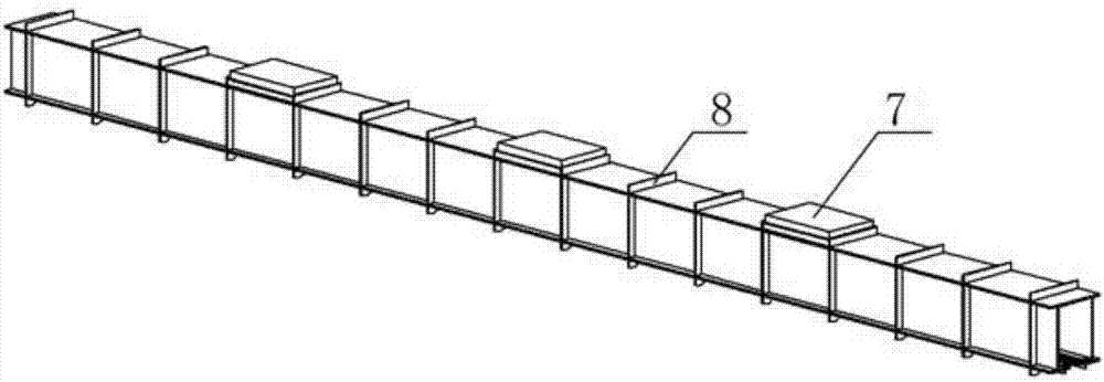
[0064] A suspended monorail traffic track beam, the track beam includes a track beam top plate 1, a track beam web 2 and a track beam bottom plate 3, two sets of track beam webs 2 are arranged, and two sets of track beam webs 2 are left and right The ground is connected to the left and right sides of the track beam top plate 1, and the track beam top plate 1 and the track beam web 2 are connected to form a “П”-shaped structure. Track beam bottom plates 3 are arranged on the inner side walls of the two sets of track beam webs 2, and the two sets of track beam bottom plates 3 are arranged parallel to the track beam top plate 1, and the sum of the widths of the two sets of track beam bottom plates 3 is smaller than the track beam top plate 1 Width, so that there is a certain distance between the track beam bottom plate 3 on the left side and the track beam bottom plate 3 on the right side. A set of track beam top plates 1, two sets of track beam web plates 2 and two sets of track...

Embodiment 2

[0066]On the basis of Embodiment 1, the rubber damping pad 5 is set as a split structure, mainly including a main damping pad 52 and a secondary damping pad 51. The cross section of the vibrating pad is trapezoidal, preferably isosceles trapezoidal. The auxiliary shock absorbing pad 51 is arranged in a triangular prism structure, and the cross section of the auxiliary shock absorbing pad 51 is an isosceles triangle. The hypotenuse of this isosceles triangle is equal to the slope length of the isosceles trapezoidal section of the main vibration damping pad 52, and the slopes of the two groups of secondary vibration damping pads 51 are attached to the slopes on both sides of the main vibration damping pad 52 with one left and one right. form a cuboid structure.

Embodiment 3

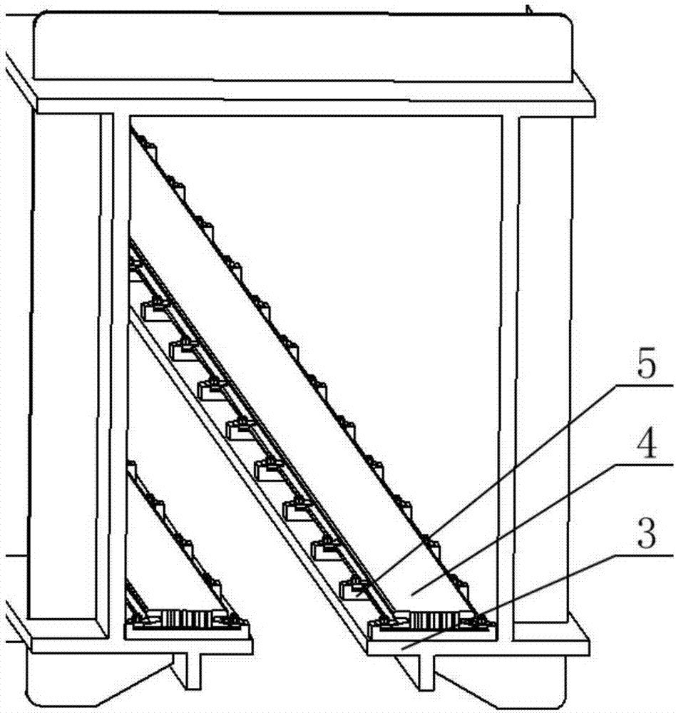
[0068] On the basis of Embodiment 1 or Embodiment 2, multiple sets of rail support platforms 9 are arranged on the upper surface of the track beam bottom plate 3 , and the multiple sets of rail support platforms 9 are evenly distributed along the length direction of the track beam bottom plate 3 . The upper surface of each group of rail platform 9 is provided with a rubber pad placement groove, the length of the rubber pad placement groove is equal to the length of the bottom edge of the main vibration damping pad 52 of the rubber vibration damping pad 5, and the vibration damping rubber pad 5 is placed on the corresponding The rubber pad of the rail platform 9 is placed in the groove. Preferably, the rubber pad placement grooves on each set of rail platforms 9 are set in the middle of the corresponding rail platforms 9 .


PUM


Abstract

The invention discloses a suspended type monorail transit track beam, belongs to the technical field of rail traffic and aims at providing the suspended type monorail transit track beam. By improvingthe vibration absorbing performance of the suspended type monorail transit track beam, the train running comfort is improved. The suspended type monorail transit track beam comprises a track beam topplate, track beam web plates and track beam bottom plates, wherein the track beam web plates are arranged on the left and right sides of the track beam top plate, and the track beam bottom plates arearranged on the internal side walls of the track beam web plates; vibration absorbing rubber pads are arranged on the track beam bottom plates; running rails are arranged on the vibration absorbing rubber pads; and the running rails are connected to the track beam bottom plates through fastener systems. The suspended type monorail transit track beam is applicable to the suspended type monorail transit track beams.

Description

technical field [0001] The invention belongs to the technical field of rail transit, and relates to a suspended monorail rail beam. Background technique [0002] Suspended monorail transit is a new type of rail transit system. It has the advantages of strong climbing ability, small curve passing radius, low cost, low noise, short construction period, and small footprint. It can meet short-distance and small-to-medium passenger flow transportation tasks. Suspended monorail transportation is suitable for the extension and connecting lines of the secondary and main lines of public transportation in large cities, the main public transportation lines of small and medium-sized cities, the connecting lines from airports, high-speed rail, and intercity railway stations to the city center or scenic spots, and large-scale natural tourist attractions Lines and intra-area connecting lines and other ranges. [0003] The invention patent with the application number 201710059568.4 disclo...

Claims


Application Information

Patent Timeline
Patent Type & Authority Applications(China)
IPC IPC(8): E01B25/24
CPCE01B25/24
Inventor 何庆烈蔡成标朱胜阳张水清王明昃翟婉明何飞林秋君张龙庆徐翔何春燕陈兆玮张嘉伟杨尚福冯洋袁玄成韩兆令
Owner SOUTHWEST JIAOTONG UNIV
Why Eureka
Try Eureka