Novel fuel oil distributor applying combined valve element

A technology of fuel distributor and combined spool, which is applied in the direction of fuel valves of gas turbine devices, machines/engines, turbines/propulsion devices, etc., which can solve the problems of heavy processing tasks, unfavorable for engines, and large number of parts, etc., and achieve reduction Effects of machining tasks, reduced number of valve components, reduced product quality

Active Publication Date: 2018-05-08
BEIJING HANGKE ENGINE CONTROL SYST SCI & TECH
View PDF5 Cites 8 Cited by
  • Summary
  • Abstract
  • Description
  • Claims
  • Application Information

AI Technical Summary

Problems solved by technology

However, it will inevitably lead to problems such as complex structure, large number of parts, heavy processing tasks and high weight.
Not conducive to engine weight reduction

Method used


Image

  • Novel fuel oil distributor applying combined valve element
  • Novel fuel oil distributor applying combined valve element
  • Novel fuel oil distributor applying combined valve element

Examples


Embodiment Construction

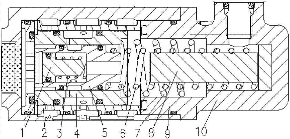
[0014] The combination spool requires strict control over the assembly process. Now take the rightward direction of the inner hole of the shell as the benchmark, such as figure 2 As shown, first install the check valve 1 and the check valve spring 3 into the main oil circuit spool 5 with the tip of the spool facing right to form the main oil circuit spool assembly; then press the main oil circuit spool assembly Install one end of the step in the right direction into the auxiliary oil circuit spool 4 to form the auxiliary oil circuit spool assembly; then install the auxiliary oil circuit spool assembly in the valve sleeve 2 with the end with the inner step facing right to form the valve sleeve assembly; then put the valve sleeve assembly into the housing 9 to the left; finally install the housing cover 10 that has been loaded into the spring seat 8, auxiliary oil circuit spring 7, and main oil circuit spring 6 in sequence on the housing 9. After each installation step, check ...


PUM


Abstract

The invention belongs to the field of mechanical hydraulic structure design for aircraft engine accessories. The invention discloses a novel fuel oil distributor applying a combined valve element. A check valve 1 and a check valve spring 3 are installed into a main oil channel valve element 5 in a direction from the tip end of the valve element to the right to form a main oil channel valve elementassembly 5; then the main oil channel valve element assembly is installed into an auxiliary oil channel valve element 4 in a direction from one end with steps to the right to form an auxiliary oil channel valve element assembly; then the auxiliary oil channel valve element assembly is installed into a valve sleeve 2 in a direction from one end with inner steps to the right to form a valve sleeveassembly; then the valve sleeve assembly is installed into a shell body 9 towards the left; and finally a shell body cover 10 which is already provided with a spring seat 8, an auxiliary oil channel spring 7 and a main oil channel spring 6 in sequence is installed onto the shell body 9. The novel fuel oil distributor disclosed by the invention is compact and simple in structure, and capable of reducing the number of parts and the weight of a product in the case of meeting the same use requirement, so that the response speed of valve opening is increased.

Description

technical field [0001] The invention belongs to the field of mechanical hydraulic structure design of aircraft engine accessories. Background technique [0002] Such as figure 1 , 3 As shown, the current fuel distributors in aircraft engine accessories are all required to provide fuel with a certain pressure and flow for dual oil nozzles or more oil nozzles. Therefore, most of the designs are double valve assemblies or more valve assemblies, so as to realize oil supply under different opening pressures. However, it will inevitably lead to problems such as complex structure, large number of parts, heavy processing tasks and high weight. Not conducive to engine weight loss. Contents of the invention [0003] The object of the present invention is to invent a new type of fuel distributor using a combined spool, which can make the structure compact and simple, reduce the number of parts, reduce the weight of the product, and improve the response speed of the valve opening ...

Claims


Application Information

Patent Timeline
Patent Type & Authority Applications(China)
IPC IPC(8): F02C7/228F02C7/232
Inventor 国宝春宋学洋阮杰李海涌
Owner BEIJING HANGKE ENGINE CONTROL SYST SCI & TECH
Why Eureka
Try Eureka