Pneumatic pilot type explosion pressure relief device

A pressure relief device, pilot-operated technology, applied in the direction of valve device, valve operation/release device, function valve type, etc., can solve the problems of plastic deformation of the bursting disc, untimely response, time-consuming, laborious, etc., to achieve safe and accurate release The effect of small storage and maintenance workload and compact overall structure

Pending Publication Date: 2018-05-08
BEIJING AEROSPACE PETROCHEM TECH & EQUIP ENG CORP LTD
View PDF6 Cites 0 Cited by
  • Summary
  • Abstract
  • Description
  • Claims
  • Application Information

AI Technical Summary

Problems solved by technology

Conventional safety valves do not perform well under low-pressure conditions, and are not suitable for conditions where the pressure is lower than 100 kPa. There are many problems such as inaccurate opening pressure, large excess pressure, and untimely response.
Although the bursting disc has good sealing performance and quick response, because of its direct contact with the medium, its discharge pressure is greatly affected by the corrosiveness and temperature of the medium, especially in low temperature conditions such as LNG, the opening pressure deviation of the bursting disc will be very large ; and when the pressure fluctuates or circulates, the stress of the rupture disc often reaches above the yield limit and is prone to plastic deformation, which in turn leads to changes in its physical properties, premature blasting, and a large deviation in opening pressure
[0004] In addition, once the conventional safety valve and bursting disc pressure relief device releases pressure, the production system must be shut down and disassembled for recalibration or replacement. Maintenance is time-consuming and laborious, which is not compatible with the current long-term operation and improvement of production efficiency. highly disproportionate demands

Method used


Image

  • Pneumatic pilot type explosion pressure relief device
  • Pneumatic pilot type explosion pressure relief device
  • Pneumatic pilot type explosion pressure relief device

Examples


Embodiment Construction

[0053] The present invention will be described in further detail below in conjunction with the accompanying drawings and specific embodiments.

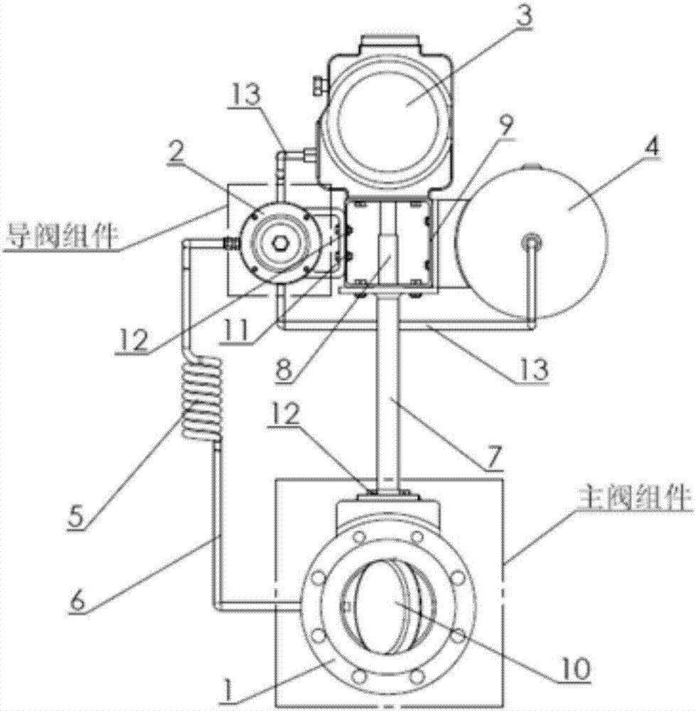
[0054] Such as figure 1 A pneumatic pilot blasting pressure relief device shown includes a main valve 1, a pilot valve 2, a pneumatic actuator 3, an energy storage tank 4, a heat exchange tube 5 and connecting pipelines.

[0055] The main valve 1 is composed of a main valve body, a main valve stem sleeve 7 , a main valve stem 8 and a main valve disc 10 . The main valve disc 10 and the main valve body have a metal sealing structure, which can be applied in the ultra-low temperature working condition of -196°C to the high temperature working condition of 538°C. The main valve stem sleeve 7 is arranged on the outer side of the main valve stem 8, and the main valve stem sleeve 7 is fixedly connected with the main valve body through a hex head bolt-12. The lower end of the main valve stem 8 is connected to the main valve disc 10, and the...


PUM


Abstract

The invention relates to the technical field of valve design, and particularly discloses a pneumatic pilot type explosion pressure relief device. The pressure relief device comprises a main valve, a pilot valve arranged above the main valve, a pneumatic executing mechanism, an energy storage tank and a heat exchange tube, wherein the pneumatic executing mechanism and the energy storage tank communicate with the pilot valve through an instrument air pipeline correspondingly, and the heat exchange tube is arranged between the main valve and the pilot valve. The device is compact in overall structure, and a pressure relief triggering mechanism and a sealing structure are guaranteed to have relatively high reliability under the ultra-low temperature and high-temperature harsh working conditions; and meanwhile, the pressure relief state of the device is easy to observe, the maintenance workload is small, the shutdown cost is low, high precision is obtained, and the device can replace a conventional safety valve and a rupture disk in some specific occasions.

Description

technical field [0001] The invention belongs to the technical field of valve design, and in particular relates to a pneumatic pilot blasting pressure relief device. Background technique [0002] At present, pressure relief devices are widely used in various sectors of the national economy such as petroleum, chemical industry, power station, metallurgy, nuclear power, and national defense. With the improvement of production efficiency, relevant departments and enterprises have increasingly stringent requirements on environmental protection and safety. As an essential part of the emergency relief system, the performance and sealing requirements of the pressure relief device providing overpressure protection are also more stringent. [0003] Taking the ground flare system in the petrochemical industry as an example, the medium is usually flammable, explosive, poisonous and harmful chemical substances, and the operating pressure is relatively low, generally several thousand Pa ...

Claims


Application Information

Patent Timeline
Patent Type & Authority Applications(China)
IPC IPC(8): F16K17/02F16K1/22F16K31/36
CPCF16K1/221F16K17/02F16K31/36
Inventor 范军郭善刚周浩岳大皓陈殿京莫力根刘尹张散荣
Owner BEIJING AEROSPACE PETROCHEM TECH & EQUIP ENG CORP LTD
Why Eureka
Try Eureka