Heat pump system and control method of heat pump system

A heat pump system and control valve technology, applied in the field of heat exchange, can solve the problems of low defrosting heat, reliability problems, heat loss, etc., to increase evaporation heat absorption, improve defrosting effect, and reduce heat loss Effect

Inactive Publication Date: 2018-05-08
GREE ELECTRIC APPLIANCES INC
View PDF15 Cites 6 Cited by
  • Summary
  • Abstract
  • Description
  • Claims
  • Application Information

AI Technical Summary

Problems solved by technology

[0004] However, this technical solution still has the following deficiencies: in the bypass defrosting process, the high-temperature and high-pressure gaseous refrigerant is used in the connecting pipes of the internal and external units, and there is no cut-off.
But in the invention image 3 , 4 In the two defrosting modes, the refrigerant passes through the indoor side during the defrosting process, and the indoor fan is still running at the same time, with heating output. The heat is not only supplied to the room, but also used to remove the frost on the outdoor heat exchanger. The defrosting heat is small, and the two heat exchangers have to be switched, the defrosting time is long, the defrosting efficiency is low, it is not conducive to defrosting, and the system and control are more complicated
At the same time, the solution of this invention cannot well solve the problem of heat loss on the connecting pipeline of the internal and external machines during defrosting under the condition of low-temperature long-connected pipes; Figure 5 The defrosting mode shown is direct bypass defrosting, there is no evaporator heat absorption process, the defrosting heat is small, and reliability problems are prone to occur;

Method used


Image

  • Heat pump system and control method of heat pump system
  • Heat pump system and control method of heat pump system
  • Heat pump system and control method of heat pump system

Examples


Embodiment Construction

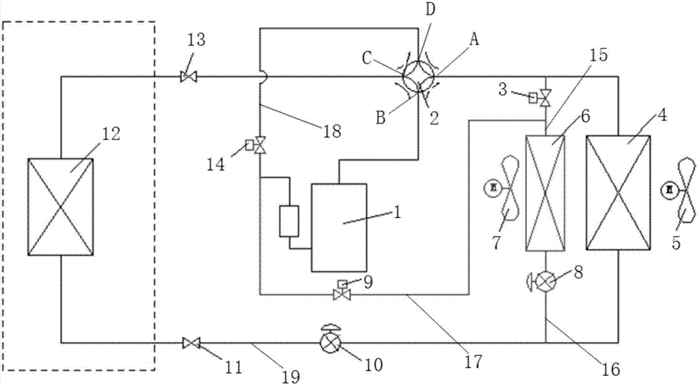
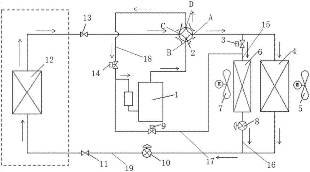
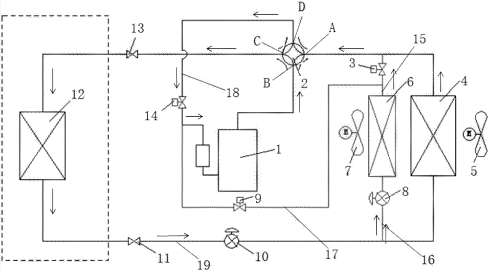
[0037] Hereinafter, the present invention will be described in detail with reference to the drawings and in conjunction with the embodiments.

[0038] Combine figure 1 , figure 2 , image 3 , Figure 4 with Figure 5 As shown, the heat pump system in the embodiment of the present application includes a compressor 1, an indoor heat exchanger 12, and an outdoor heat exchanger 4 connected in series on a circulating pipeline. The heat pump system further includes: an auxiliary heat exchanger 6; a first control pipeline 15. The first end and the second end of the first control pipe 15 are respectively connected to the first end of the outdoor heat exchanger 4 and the first end of the auxiliary heat exchanger 6; the second control pipe 16, the second control pipe The first end and the second end of the circuit 16 are respectively connected to the second end of the outdoor heat exchanger 4 and the second end of the auxiliary heat exchanger 6; the third control pipeline 17, the first end...


PUM


Abstract

The invention provides a heat pump system and a control method of the heat pump system. The heat pump system comprises a compressor, an indoor heat exchanger, an outdoor heat exchanger, an auxiliary heat exchanger, a first control pipeline, a second control pipeline, a third control pipeline and a control valve; the first control pipeline is connected with the first end of the outdoor heat exchanger and the first end of the auxiliary heat exchanger, the first end and the second end of the second control pipeline are connected with the second end of the outdoor heat exchanger and the second endof the auxiliary heat exchanger, the first end of the third control pipeline is connected with the first end of the outdoor heat exchanger and the first end of the auxiliary heat exchanger at the same time, the second end of the third control pipeline is connected with an air inlet of the compressor. The control valve has a first work state for enabling the auxiliary heat exchanger to be in series connection with the outdoor heat exchanger through the third control pipeline. According to the heat pump system and the control method of the heat pump system, heat losses under the defrosting state are few, and the defrosting effect is better.

Description

Technical field [0001] The present invention relates to the field of heat exchange technology, in particular to a heat pump system and a control method of the heat pump system. Background technique [0002] When the heat pump system is running in the winter heating mode, frost often appears on the surface of the outdoor heat exchanger. The frost layer will reduce the heating capacity of the heat pump system, and even cause the heat pump system to malfunction. [0003] In order to solve the above problems, an application number "201320568886.0", titled "an improved defrosting device for air source heat pump" is published in the Chinese Patent Library, which discloses that the defrosting device is defrosted by setting a bypass In the defrosting process, the refrigerant passes through the outdoor heat exchanger from the exhaust gas and directly returns to the compressor. [0004] However, this technical solution still has the following shortcomings: in the bypass defrosting process, t...

Claims


Application Information

Patent Timeline
IPC IPC(8): F25B30/02F25B47/02F25B49/02
CPCF25B30/02F25B47/02F25B49/02F25B2347/02
Inventor 胡锐胡强杨健杨玉生王永立
Owner GREE ELECTRIC APPLIANCES INC
Why Eureka
Try Eureka