
Multichannel differential-pressure-type airtight leak detector and leak detection method

A differential pressure, multi-channel technology, applied in the direction of measuring the increase and decrease rate of the fluid, using the liquid/vacuum degree to measure the liquid tightness, etc., can solve the problems of high cost, different pressure difference, and no reference object, etc., to achieve The effect of low instrument cost

Active Publication Date: 2018-05-08
BOYI TIANJIN PNEUMATIC TECH INST
View PDF7 Cites 5 Cited by
  • Summary
  • Abstract
  • Description
  • Claims
  • Application Information

AI Technical Summary

Problems solved by technology

[0004] 1. A reference object is required as a reference point, and in some cases there is no reference object available;
[0005] 2. It is not applicable to the situation where the temperature and other conditions of the reference object and the measured object are different, because when the temperature and other conditions of the reference object and the measured object are different, the pressure changes on each side caused by the influence of temperature are different, resulting in a difference caused by non-leakage. pressure, affecting leak detection;
[0006] 3. It is not suitable for the situation where the temperature and other conditions of the measured object change gradually, because when the temperature and other conditions of the measured object are different at different times for a long time, the temperature difference between the temperature of the measured object and the environment will affect the heat dissipation speed, so the heat dissipation The pressure difference generated will be different, which will affect the leak detection;
[0007] 4. The gas path is complicated, there are many components and the cost is high

Method used


Image

  • Multichannel differential-pressure-type airtight leak detector and leak detection method

Examples


Embodiment Construction

[0036] It should be noted that, in the case of no conflict, the embodiments of the present invention and the features in the embodiments can be combined with each other.

[0037] In describing the present invention, it should be understood that the terms "center", "longitudinal", "transverse", "upper", "lower", "front", "rear", "left", "right", " The orientations or positional relationships indicated by "vertical", "horizontal", "top", "bottom", "inner" and "outer" are based on the orientations or positional relationships shown in the drawings, and are only for the convenience of describing the present invention and Simplified descriptions, rather than indicating or implying that the device or element referred to must have a particular orientation, be constructed and operate in a particular orientation, and thus should not be construed as limiting the invention. In addition, the terms "first", "second", etc. are used for descriptive purposes only, and should not be understood ...


PUM


Abstract

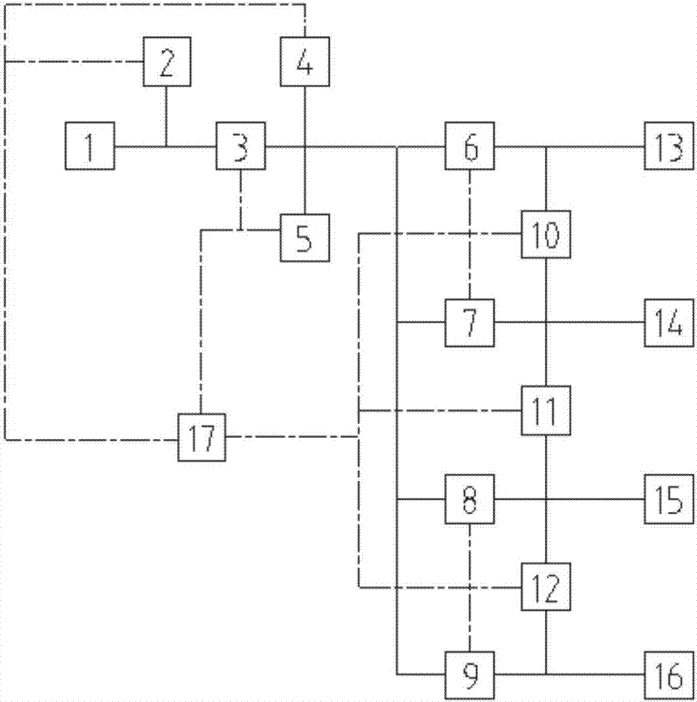
The invention provides a multichannel differential-pressure-type airtight leak detector and leak detection method. The leak detector comprises a control unit, an air source interface, a charging valveand balance valves. The air source interface and the charging valve are connected and a first pressure sensor is connected between the two. The charging valve and the balance valves are connected, and a second pressure sensor and an exhaust valve are connected between the two. There are several balance valves. An output terminal of the charging valve is connected to the plurality of balance valves through a bifurcation pipe so as to form multiple channels. Tail ends of the channels are connected to measured objects through measured object interfaces. A differential pressure sensor is arrangedbetween the measured objects of each two channels. Each differential pressure sensor is located between the balance valve and the measured object of each channel. The control unit is electrically connected to the charging valve, the balance valves, the exhaust valve, the first pressure sensor, the second pressure sensor and the differential pressure sensors. In the invention, each channel is connected to the measured objects of a same batch, the measured objects are taken as references to each other and leak detection is performed, and a primary standard substance is not needed so that the leak detector is not influenced by the primary standard substance and instrument cost is low.

Description

technical field [0001] The invention belongs to the technical field of airtight leak detection, and in particular relates to a multi-channel differential pressure airtight leak detector and a leak detection method. Background technique [0002] The existing differential pressure airtight leak detectors are generally single-channel type, refer to "GBT 25752-2010 Differential pressure airtight leak detectors". The differential pressure airtight leak detector uses the reference object (a non-leaking workpiece or metal can) as the reference end and the comparison end. Assuming that the reference object side does not leak, if there is a differential pressure, there will be leakage on the measured object side. When multi-channel use is required, it is generally realized by using multiple single-channel leak detectors to work at the same time; some multi-channels share the same inflation and exhaust circuit (that is, pressurized exhaust valve) to reduce costs, but the differential ...

Claims


Application Information

Patent Timeline
Patent Type & Authority Applications(China)
IPC IPC(8): G01M3/26
CPCG01M3/26
Inventor 刘德亮赵超越
Owner BOYI TIANJIN PNEUMATIC TECH INST
Learn More