Remote connection system for an aircraft

Active Publication Date: 2016-06-23
SN DETUDE & DE CONSTR DE MOTEURS DAVIATION S N E C M A
View PDF3 Cites 5 Cited by
  • Summary
  • Abstract
  • Description
  • Claims
  • Application Information

AI Technical Summary

Benefits of technology

[0024]It is thus possible to reduce significantly the cost of instrumenting a given blade of the propeller. Specifically, this blade may be monitored merely by incorporating a light guide in said blade, neither more nor less, the light source may be arranged remotely from this blade, in particular in the vicinity of the engine axis, and the light beam may be emitted from the emission surface of this blade after propagating along the light guide between the light source and this emission surface.
[0025]Furthermore, this configuration enables a light beam to be emitted f

Problems solved by technology

Specifically, fatigue in a blade may lead to irreversible damage to the engine if it is not predicted soon enough.
Nevertheless, such deformation gauges are difficult to install and they are expensive, particularly since they generally present a lifetime that is short.
Installing them on the blades of an engine in operation remains difficult because of the need to provide power and instrumentation on an engine that is rotating.
Strain gauges are used for that purpose, but only to monitor blades that have been removed from an engine hub, which monitoring takes place un

Method used


Image

  • Remote connection system for an aircraft
  • Remote connection system for an aircraft
  • Remote connection system for an aircraft

Examples


first embodiment

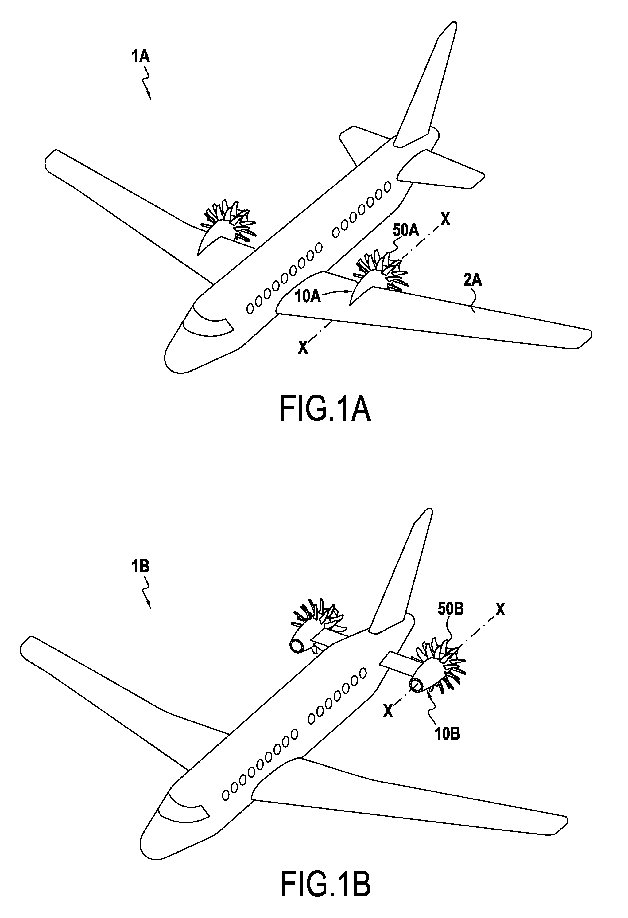
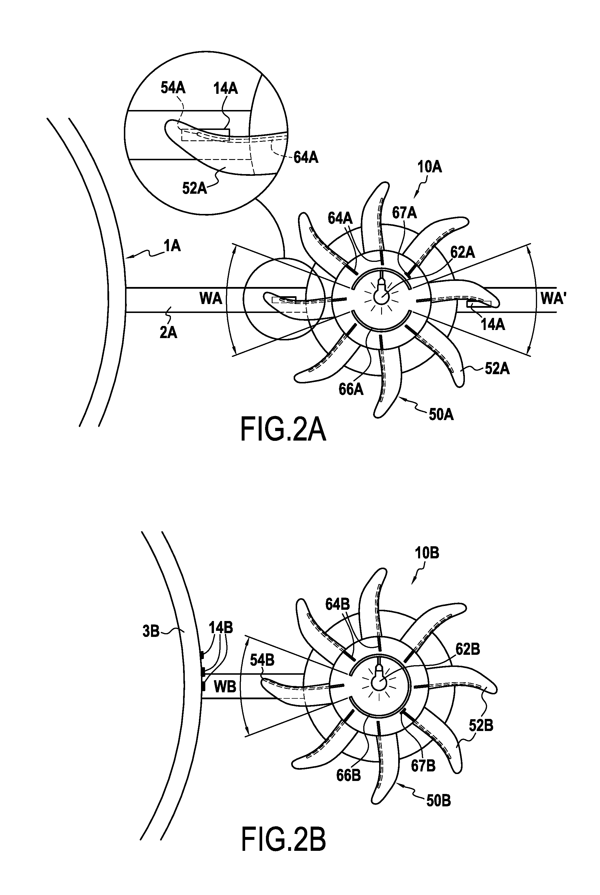
[0051]FIGS. 1A, 2A, and 3A are highly schematic views showing a first embodiment in accordance with the present disclosure of an aircraft 1A having two assemblies, each provided with a remote connection system.

second embodiment

[0052]FIGS. 1B, 2B, and 3B are highly schematic views showing a second embodiment in accordance with the present disclosure of an aircraft 1B having two assemblies, each provided with a remote connection system.

third embodiment

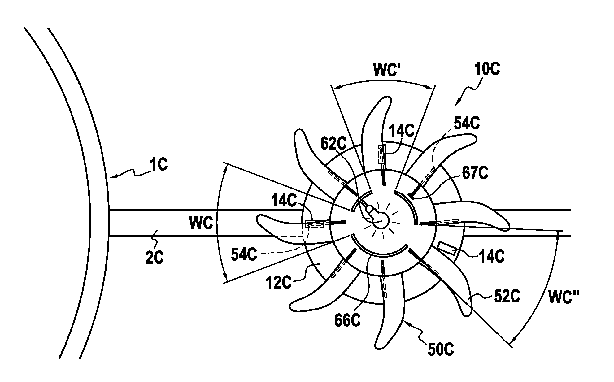
[0053]FIG. 4 is a highly schematic view of a third embodiment in accordance with the present disclosure of an aircraft 1C having two assemblies, each provided with a remote connection system.

[0054]These first, second, and third embodiments present characteristics that are very analogous, so they are described simultaneously, for the sake of concision in the present disclosure. The numerical references relating to the first embodiment are given the suffix -A, whereas the numerical references given to the second embodiment are given that the suffix -B. Finally, the numerical references relating to the third embodiment are given the suffix -C.

[0055]In each of these three embodiments, the aircraft 1A, 1B, 1C includes two assemblies that are selected to be identical (form which it may be departed without departing from the scope of the present disclosure), such that only one of the two assemblies is described in detail, likewise for the sake of concision in the present disclosure.

[0056]I...


PUM


Abstract

The present description relates to a remote connection system suitable for being incorporated in an aircraft (1A, 1B, 1C) comprising at least one engine propeller (50A, 50B, 50C) having a plurality of blades (52A, 52B, 52C) suitable for rotating relative to a stationary module (10A, 10B, 10C) of the aircraft about an engine axis (X). The remote connection system comprises: a light emitter device configured, when the remote connection system is incorporated in the aircraft (1A, 1B, 1C), to emit a light beam that emerges to the outside of the propeller (50A, 50B, 50C), from at least one emission surface (54A, 54B, 54C) of said propeller (50A, 50B, 50C).

Description

FIELD OF THE INVENTION[0001]The present description relates to aircrafts, and it relates more particularly to the field of monitoring the health of blades of such engines, enclosed or not in a housing.STATE OF THE PRIOR ART[0002]The health of aircraft engine blades is often a critical factor that needs to be monitored, in particular when the blades are subjected to high levels of stress, as for example with the blades enclosed or not in a housing of turbine engines such as turboprops. Specifically, fatigue in a blade may lead to irreversible damage to the engine if it is not predicted soon enough.[0003]A traditional technique for performing such monitoring consists in performing strength tests with deformation gauges.[0004]Nevertheless, such deformation gauges are difficult to install and they are expensive, particularly since they generally present a lifetime that is short. Installing them on the blades of an engine in operation remains difficult because of the need to provide powe...

Claims


Application Information

Patent Timeline
IPC IPC(8): G01N21/88F01D21/00G01N21/21
CPCG01N21/8806G01N21/21F01D21/003G01N2201/08G01N2201/0683G01N2201/061G01N2021/8848B64C11/26B64D2045/0085B64D2027/005Y02T50/60B64C27/46B64D45/00B64D47/00
Inventor NICQ, GEOFFROY
Owner SN DETUDE & DE CONSTR DE MOTEURS DAVIATION S N E C M A
Why Eureka
Try Eureka