
Novel solid-state matrix switch system

A matrix switch, solid-state technology, applied in the field of high-index solid-state matrix switch systems, can solve the problems of large system design loss, poor reliability, limited service life, etc., and achieve the effect of high integration

Active Publication Date: 2018-09-11
NANJING GUORUI ANTAIXIN TECH
View PDF12 Cites 5 Cited by
  • Summary
  • Abstract
  • Description
  • Claims
  • Application Information

AI Technical Summary

Problems solved by technology

[0003] Early matrix switching systems mainly used relays as channel switching switches, but the frequency of the relays was not high, and the connection and disconnection were realized by mechanical contact contact, and the mechanical life was only 100,000 times.
At the same time, it is limited by the high frequency characteristics of PCB microwave boards
Therefore, the upper limit of the operating frequency can only reach 3GHz, and the loss of the system design is large, the size cannot be miniaturized, and the service life is limited
[0004] The current matrix switch system, considering the contradiction between the loss of radio frequency signals and the isolation index, the product size is relatively large
At the same time, most of the ports are designed with microwave glass insulators, resulting in poor reliability

Method used


Image

  • Novel solid-state matrix switch system
  • Novel solid-state matrix switch system
  • Novel solid-state matrix switch system

Examples


Embodiment Construction

[0047] The present invention will be described in further detail below in conjunction with the accompanying drawings.

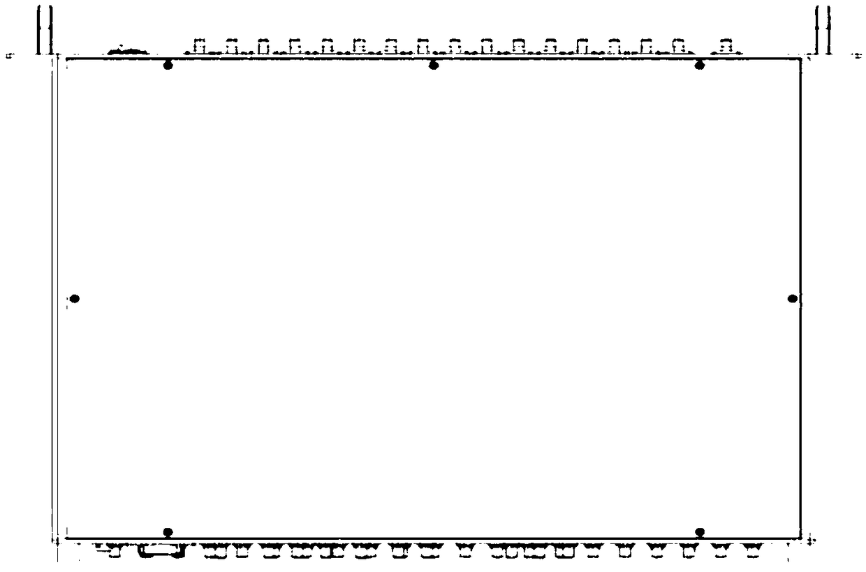
[0048] The complete product designed by the present invention is as figure 1 As shown, the overall appearance is flat, and the product height is designed according to the 1U standard. Easy to carry and place in a standard case. The front and rear panels are designed as figure 2 and image 3 shown. The panel design is compact, the layout is beautiful, the visual effect is good, and it is also easy to disassemble and replace.

[0049] Such as Figures 1 to 9 As shown, the present invention provides a novel solid-state matrix switch system, including an ARM main control board module, a digital display module, and a main switch module.

[0050] The principle design of the ARM main control board module adopts the design of the ARM embedded development board. The core device is Samsung's S3C2416XH chip. This chip is a 32BIT processor with ARM9 as the core, w...


PUM

PropertyMeasurementUnit
Plate thicknessaaaaaaaaaa
Thicknessaaaaaaaaaa

Abstract

The invention discloses a novel solid-state matrix switch system. A main switch module comprises a downlink channel, wherein radio frequency signals are input from the ANT, and then are output to PM after passing through the channel switch A and a downlink matrix switch; an uplink channel, wherein radio frequency signals are input from SG, and are divided into eight paths of independent radio frequency signals through a 1-8 broadband power dividing circuit, and is transmitted to an ANT through an uplink additional matrix switch, a channel switch B and a channel switch A; an additional channel,wherein radio frequency signals are input from the SG, and after passing through the power divider circuit, are transmitted to the BANT after passing through the uplink additional matrix switch and the channel switch B; a calibration and backup channel, wherein the radio frequency signals are respectively input from the CAL, the BAK1, and BAK2, and are transmitted to the PM after entering into the calibration and backup matrix switch; a micro-strip coupling circuit, wherein the radio frequency signals are input from an SG end, and output in the form of two paths of signals after passing through the micro-strip coupling circuit, wherein one path of main path signal enters into the power dividing circuit, and the signal after coupling sampling is output to the Couple.

Description

technical field [0001] The invention relates to a high-index solid-state matrix switch system, which is used for signal circulation and switching between testing instruments and tested parts, and is a device for displaying IP addresses and connecting to an upper system through a network port. Background technique [0002] In the automatic test system, the matrix switch system is mainly a device for switching and combining multiple input or output signals, especially in the field of automated test for radio frequency mass production. [0003] Early matrix switching systems mainly used relays as channel switching switches, but the frequency of relays was not high, and mechanical contacts were used to achieve connection and disconnection, and the mechanical life was only 100,000 times. At the same time, it is limited by the high frequency characteristics of PCB microwave boards. Therefore, the upper limit of the operating frequency can only reach 3GHz, and the loss of the syst...

Claims


Application Information

Patent Timeline
IPC IPC(8): G05B19/042
CPCG05B19/0423G05B2219/21116G05B2219/21168
Inventor 钟景华唐毅张燕
Owner NANJING GUORUI ANTAIXIN TECH
Learn More