Three-dimensional guidance law identification filtering method based on IMM_UKF
A guidance law and three-dimensional technology, applied in special data processing applications, instruments, electrical digital data processing, etc., can solve the problems of reduced guidance accuracy and changes in motion models, and achieve the effect of improving guidance accuracy
- Summary
- Abstract
- Description
- Claims
- Application Information
AI Technical Summary
Problems solved by technology
Method used
Image
Examples
specific Embodiment approach 1
[0046] Specific implementation mode 1: The specific process of the three-dimensional guidance law identification and filtering method based on IMM_UKF in this implementation mode is as follows:
[0047] Step 1, establish the relative motion equation of evader and pursuer;
[0048] The pursuer is an enemy intercept missile, and the evader is a target aircraft;
[0049] Step 2, based on the relative motion equation of the evader and the pursuer established in step 1, establish the relative motion model of the evader relative to the pursuer;
[0050] Step 3, based on the pursuer motion model relative to the evader established in step 2, design the IMM filter on the evader;
[0051] The IMM filter is an interactive multi-model filter.
specific Embodiment approach 2
[0052] Specific embodiment two: the difference between this embodiment and specific embodiment one is: the relative motion equation of evader and pursuer is established in said step one; The specific process is:
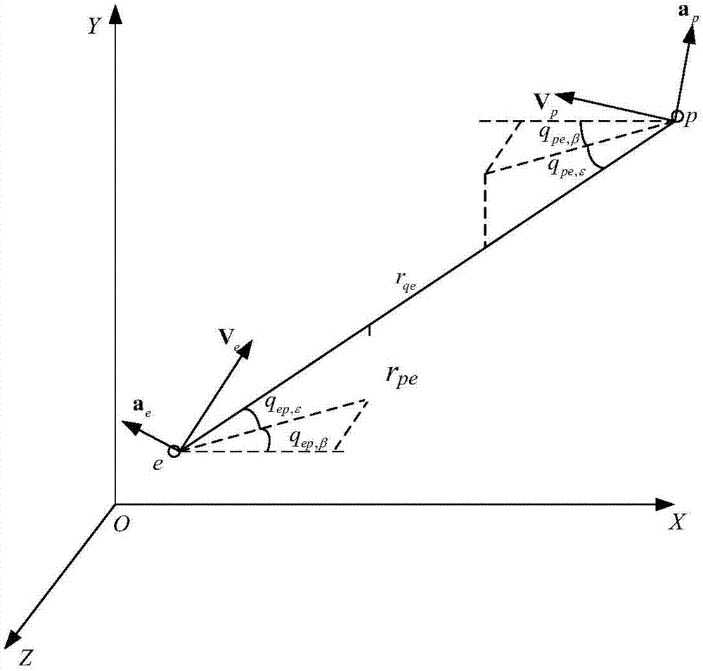
[0053] The scene inertial coordinate system OXY is defined as the initial line-of-sight coordinate system of the target aircraft evader; figure 1 It shows the relative motion relationship between evader and pursuer on the plane.
[0054] The target aircraft evader and the enemy interceptor missile pursuer are denoted by e and p respectively;
[0055] The evader inertial coordinate system coincides with the scene inertial coordinate system; the origin and y-axis of the pursuer inertial coordinate system coincide with the scene coordinate system, and the x-axis direction of the pursuer inertial coordinate system is opposite to the x-axis direction of the scene inertial coordinate system;
[0056] V e is the velocity vector of evader, a e is the acceleration vector ...
specific Embodiment approach 3
[0062] Specific embodiment three: the difference between this embodiment and specific embodiment one or two is: the relative motion equation of the evader and the pursuer established based on the step one in the said step two, establishes the relative motion model of the pursuer relative to the evader; the specific process is:
[0063] Suppose the pursuer uses PN guidance law to intercept the evader. The motion of the pursuer in this case is called the PN motion model. Let the pursuer state vector relative to the evader be
[0064] x=[r x ,r y ,r z ,v x ,v y ,v z ,a px ,a py ,a pz ] T (3)
[0065] where r x is the component of the distance vector of the pursuer relative to the evader along the x-axis in the scene inertial coordinate system, r y is the component of the distance vector of the pursuer relative to the evader along the y-axis in the scene inertial coordinate system, r z is the component of the distance vector of the pursuer relative to the evader alo...
PUM
 Abstract
Description
Claims
Application Information
 - R&D
- Intellectual Property
- Life Sciences
- Materials
- Tech Scout
- Unparalleled Data Quality
- Higher Quality Content
- 60% Fewer Hallucinations
Browse by: Latest US Patents, China's latest patents, Technical Efficacy Thesaurus, Application Domain, Technology Topic, Popular Technical Reports.
© 2025 PatSnap. All rights reserved.Legal|Privacy policy|Modern Slavery Act Transparency Statement|Sitemap|About US| Contact US: help@patsnap.com


