
Teaching information scanning equipment

A scanning equipment and teaching technology, applied in image communication, electrical components and other directions, can solve the problems of uneven movement speed and unstable balance of multiple area array CCDs, and achieve the effect of simple structure and guaranteed movement balance.

Inactive Publication Date: 2018-05-08
成都绿盾美佳节能科技有限公司
View PDF1 Cites 1 Cited by
  • Summary
  • Abstract
  • Description
  • Claims
  • Application Information

AI Technical Summary

Problems solved by technology

For example, the application number is: 201520328339.4, the existing scanning of manuscripts adopts an area array CCD, and multiple area array CCDs are fixed side by side on a bottom plate to form an integral face recognition unit. The gear and handle are driven by a single-side handle, which has the following problems: one-side handle drives one side of the circular gear to rotate, and because the multi-block CCD area array is large, its balance is unstable during the up and down movement process, which is extremely It is easy to cause uneven moving speed on both sides of multiple area array CCDs, which affects the use

Method used


Image

  • Teaching information scanning equipment
  • Teaching information scanning equipment

Examples


Embodiment 1

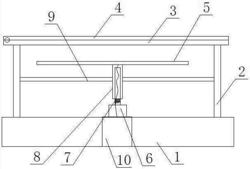
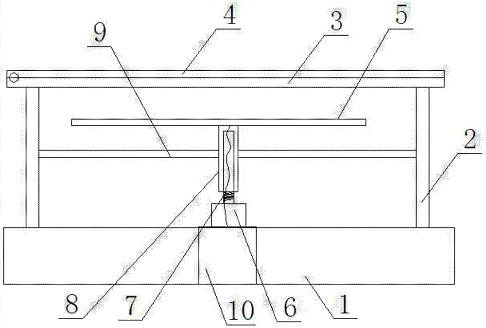
[0018] Such as figure 1 A teaching information scanning device shown includes a main cabinet 1, a pole 2 arranged at both ends of the main cabinet 1 for fixing the transparent board 3, a pressing board 4 placed above the transparent board 3, and a The area array CCD5 is used to adjust the adjusting device for adjusting the height of the area array CCD5. It is characterized in that the adjusting device includes a motor 6, a drive screw 7 connected to the output shaft of the motor 6, a lifting tube 8 sleeved outside the screw 7, a fixed The clamping plate 9 that limits the rotation of the lifting cylinder 8 is clamped between the two vertical rods 2 outside the lifting cylinder 8, and the lifting cylinder 8 is fixed on the bottom of the area array CCD5.

Embodiment 2

[0020] Based on the structure of the above-mentioned embodiment, the number of elevating cylinders 8 can be 1, 2, 3, etc. When one is used, the structure is simple. In order to improve the balance of the area array CCD, the elevating cylinder 8 is fixed at the center of the area array CCD5. When multiple, for example two, lifting tubes 8 should be distributed symmetrically to the center of the area array CCD, for example, be respectively arranged at both ends of the area array CCD5.

[0021] The motor 6 is placed on the main cabinet 1 .

[0022] Such as figure 1 , the area array CCD5 is connected with the host computer 10 through the connection line, and the screw rod 7 is provided with a threading hole and an outlet hole, and the connection line is connected with the host computer through the threading hole and the outlet hole in turn.


PUM


Abstract

The invention discloses teaching information scanning equipment. The teaching information scanning equipment comprises a main cabinet, vertical rods arranged at the two ends of the main cabinet and used for fixing a transparent plate, a pressing plate arranged above the transparent plate, an area array CCD arranged below the transparent plate and an adjusting device used for adjusting the height of the area array CCD, wherein the adjusting device comprises a motor, a drive screw connected to a motor output shaft, lifting cylinders sleeved outside the screw and fixedly arranged at the bottom ofthe area array CCD, and a clamping plate fixed outside the lifting cylinders and clamped between the two vertical rods to limit the rotation of the lifting cylinders. The screw is driven to rotate bythe motor, due to the action of the clamping plate, the screw rotates to drive the lifting cylinders to move up and down, so that the adjustment of the area array CCD is realized, and furthermore, through adoption of the structure, the structure is simple, and the moving balance of the area array CCD can be guaranteed.

Description

technical field [0001] The invention relates to the field of teaching devices, in particular to a teaching information scanning device. Background technique [0002] In modern teaching, it is often necessary to scan and identify the boss's manuscript in class and form an editable manuscript in real time. For example, the application number is: 201520328339.4, the existing scanning of manuscripts adopts an area array CCD, and multiple area array CCDs are fixed side by side on a bottom plate to form an integral face recognition unit. The gear and handle are driven by a single-side handle, which has the following problems: one-side handle drives one side of the circular gear to rotate, and because the multi-block CCD area array is large, its balance is unstable during the up and down movement process, which is extremely It is easy to cause uneven moving speed on both sides of multiple area array CCDs, which affects the use. Contents of the invention [0003] In order to sol...

Claims


Application Information

Patent Timeline
IPC IPC(8): H04N1/00H04N1/04H04N1/193
CPCH04N1/00246H04N1/00519H04N1/00559H04N1/193
Inventor 李奇宇
Owner 成都绿盾美佳节能科技有限公司
Learn More