Integrated control method and system for monitoring device and lighting device

A technology for monitoring equipment and lighting equipment, which is applied to parts of TV systems, parts of color TVs, TVs, etc., can solve problems such as energy waste and untimely switching of lighting equipment, and achieve real-time monitoring, timely and reliable monitoring, The effect of good cooperation

Active Publication Date: 2018-05-08
TRULY OPTO ELECTRONICS
View PDF9 Cites 7 Cited by
  • Summary
  • Abstract
  • Description
  • Claims
  • Application Information

AI Technical Summary

Problems solved by technology

[0004] The technical problem to be solved by the present invention is to provide an integrated control method and system for monitoring equipment and lighting equipment, which can realize integrated control of monitoring equipment and lighting equipment, realize simultaneous control of monitoring equipment and lighting equipment and ensure monitoring equipment and lighting equipment. Good coordination of lighting equipment solves the problem of energy waste caused by untimely switching of lighting equipment, and at the same time enables lighting equipment to effectively cooperate with monitoring equipment to ensure the lighting requirements of monitoring equipment and improve the monitoring performance of monitoring equipment

Method used


Image

  • Integrated control method and system for monitoring device and lighting device
  • Integrated control method and system for monitoring device and lighting device

Examples


Embodiment 1

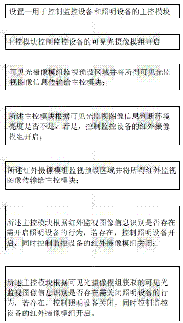
[0039] Such as figure 1 As shown, it represents a block flow diagram of an integrated control method for monitoring equipment and lighting equipment provided by the present invention. The integrated control method specifically includes the following steps:

[0040]Step 1, setting a main control module for controlling the monitoring equipment and the lighting equipment, the main control module is electrically connected with the monitoring equipment and the lighting equipment respectively;

[0041] Step 2, the main control module controls the visible light camera module of the monitoring equipment to turn on, and sets the exposure value or image brightness value of the visible light module;

[0042] Step 3. The visible light camera module monitors the preset area and transmits the visible light monitoring image information to the main control module;

[0043] Step 4, the main control module judges whether the ambient brightness is insufficient according to the visible light mo...

Embodiment 2

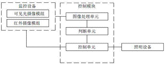
[0057] Such as figure 2 As shown, it shows a structural block diagram of an integrated control system for monitoring equipment and lighting equipment provided by the present invention, which is used to implement the integrated control method provided in the previous embodiment, including:

[0058] Monitoring equipment, lighting equipment, and a main control module; the main control module is electrically connected to the monitoring equipment and the lighting equipment, and is used to control the monitoring equipment and lighting equipment;

[0059] The monitoring equipment includes a visible light camera module and an infrared camera module;

[0060] The main control module includes an image processing unit, a judging unit and a control unit; the image processing unit is used to receive the monitoring image information acquired by the visible light camera module and the infrared camera module and extract information for judging and comparing; The judging unit is used to comp...


PUM


Abstract

The invention provides an integrated control method and a system for a monitoring device and a lighting device. The integrated control method comprises the following steps: a main control module is set; a visible light camera module of the monitoring device is controlled to be opened; whether the brightness of the environment is insufficient is judged according to visible light monitoring image information, and if yes, an infrared camera module of the monitoring device is controlled to be opened; whether to exist a behavior to open the lighting device is recognized according to the infrared monitoring image information, if yes, the lighting device is controlled to be opened, the infrared camera module is controlled to be closed, and the visible light camera module is controlled to be opened; and whether to exist a behavior to close the lighting device is recognized according to the visible light monitoring image information acquired by the visible light camera module, if yes, the lighting device is controlled to be closed, the infrared camera module is controlled to be opened, and the visible camera module is controlled to be closed. Integrated control and good matching between themonitoring device and the lighting device can be realized, and effects of achieving energy conservation and enhancing the device performance can be effectively realized.

Description

technical field [0001] The invention relates to monitoring and lighting control technology, in particular to an integrated control method and system for monitoring equipment and lighting equipment. Background technique [0002] Lighting equipment is an indispensable and important equipment in today's life, and it is widely used in various occasions such as homes, offices, and public places. Considering the extensive use of lighting equipment, the energy waste caused by untimely switching of lighting equipment during use is also amazing. In order to respond to the requirement of saving energy, the existing lighting equipment is equipped with automatic control devices, including voice-activated switches, infrared induction control and other methods. However, it is still unsatisfactory in actual use, especially in complex application scenarios, the response of the voice-activated switch is not sensitive enough, and it is easily disturbed by noise, and the timing of the switch ...

Claims


Application Information

Patent Timeline
Patent Type & Authority Applications(China)
IPC IPC(8): H04N5/232H04N5/235
CPCH04N23/60H04N23/611H04N23/70H04N23/74
Inventor 张德文
Owner TRULY OPTO ELECTRONICS
Why Eureka
Try Eureka