Injection mould utilizing moving mould pull plate to drive oblique sliders to pull cores

An injection mold and inclined slider technology, applied in the field of injection molds, can solve the problems of incomplete application of the side core pulling mechanism, affecting the service life of the mold, and large shape of the mold, so as to reduce the production cost and injection cost, prolong the service life, The effect of improving production efficiency

Active Publication Date: 2018-05-11
XIANNING HONGSHENG MOLD TECH CO LTD
View PDF9 Cites 2 Cited by
  • Summary
  • Abstract
  • Description
  • Claims
  • Application Information

AI Technical Summary

Problems solved by technology

However, when the number of side cores is large and cores need to be pulled in different directions, each side core needs a corresponding core pulling mechanism, resulting in a larger mold shape, which will also cause interference of core pulling and affect the service life of the mold
[0003] For parts with a large number of side cores and inconsistent movement directions, the traditional side core pulling mechanism is not fully applicable

Method used


Image

  • Injection mould utilizing moving mould pull plate to drive oblique sliders to pull cores
  • Injection mould utilizing moving mould pull plate to drive oblique sliders to pull cores
  • Injection mould utilizing moving mould pull plate to drive oblique sliders to pull cores

Examples


Embodiment Construction

[0021] Below in conjunction with accompanying drawing, the present invention will be further explained:

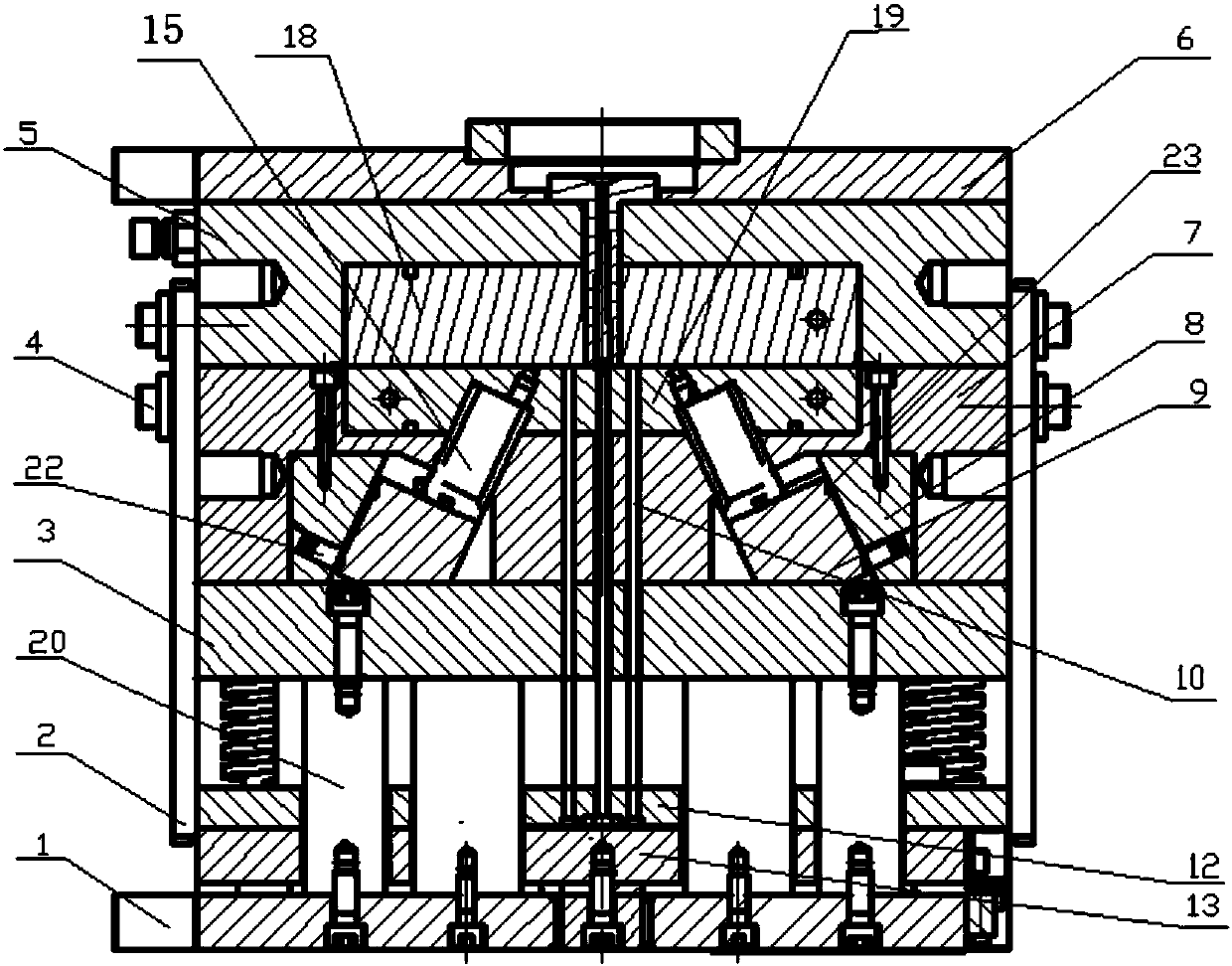
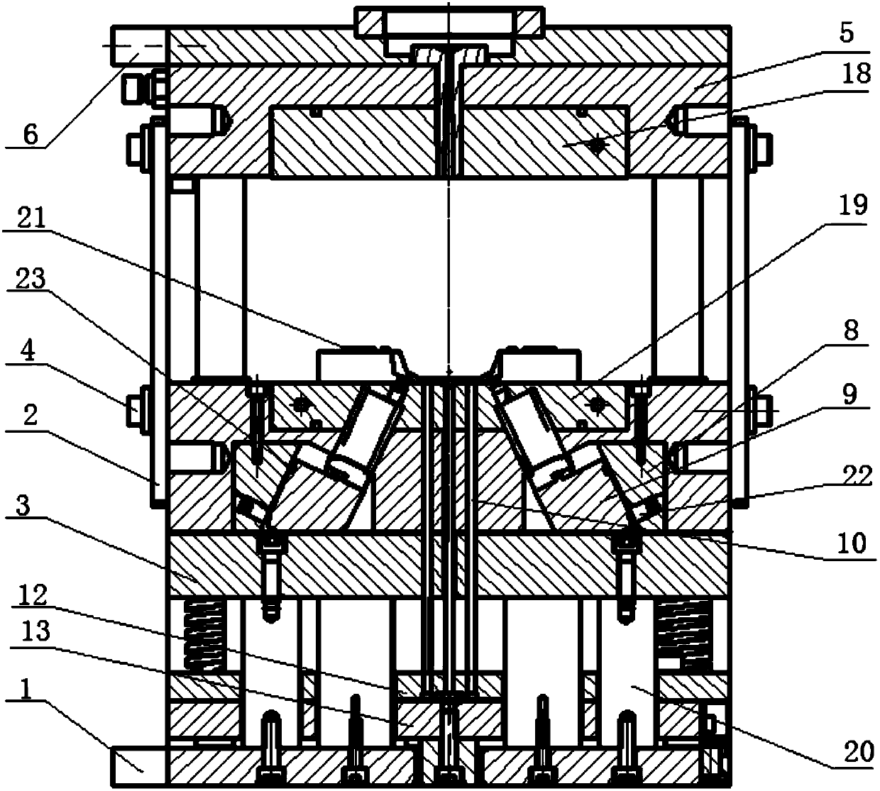
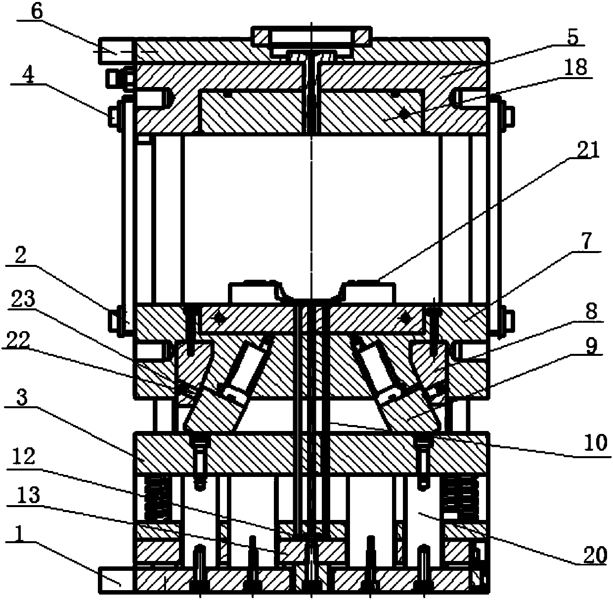
[0022] see figure 1 , the present invention includes a fixed mold part and a movable mold part, and the fixed mold part includes a fixed mold bottom plate 6 and a fixed template 5 (with a cavity 18) from top to bottom; the movable mold part includes a movable template 7 at the upper end (A core 19 corresponding to the cavity 18 is provided), the movable mold base plate 1 at the lower end and the ejection mechanism in the middle, the ejection mechanism can use existing conventional structures, such as being positioned at the top on the movable mold base plate Rod bottom plate 13, ejector rod fixing plate 12 and a plurality of push rods 10 passing through the movable mold drawing plate 3, the upper end (push rod 10) of the ejector mechanism is connected to the core 19 on the movable template 7, and the lower end passes through The movable mold bottom plate 1 is connected wi...


PUM


Abstract

The invention relates to an injection mould utilizing a moving mould pull plate to drive oblique sliders to pull cores and solves the problems of complicated structure, core pulling interference and poor synchronism, which occur when the existing injection mould is provided with lateral pulling cores in multiple directions. According to the technical scheme, the injection mould comprises a fixed mould part and a moving mould part, wherein the moving mould part comprises a moving mould plate at the upper end, a moving mould bottom plate at the lower end and an ejecting mechanism in the middle;the upper end of the ejecting mechanism is connected with a mould core on the moving mould plate, and the lower end of the ejecting mechanism penetrates through the moving mould bottom plate and is connected with a driving device; a sliding limiting mechanism is arranged between a fixed mould plate of the fixed mould part and the moving mould plate of the moving mould part; at least one lateral mould core is arranged below the moving mould plate, and the lower end of the lateral mould core is mounted on the moving mould pull plate through a connecting assembly; and the moving mould pull plateis arranged on the ejecting mechanism in a sleeving manner and connected with the moving mould bottom plate through a fixing component. The structure is very simple and compact. Lateral core pulling is simultaneously carried out in multiple different directions by adopting one core pulling mechanism. The service life is long, the production efficiency is high, and maintenance is convenient.

Description

technical field [0001] The invention relates to an injection mold, in particular to an injection mold in which a movable mold drawing plate drives an inclined slider to pull the core. Background technique [0002] For molds with side holes and undercuts on plastic products that are inconsistent with the mold opening direction, a lateral core-pulling mechanism is required to complete. Common core pulling mechanisms are inclined guide column type, inclined guide chute type and inclined slider type, etc. However, when the number of side cores is large and it is necessary to pull cores in different directions, each side core needs a corresponding core pulling mechanism, resulting in a larger mold shape, which will also cause core pulling interference and affect the service life of the mold . [0003] For parts with a large number of side cores and inconsistent movement directions, the traditional side core pulling mechanism is not completely suitable. If the above-mentioned p...

Claims


Application Information

Patent Timeline
Patent Type & Authority Applications(China)
IPC IPC(8): B29C45/26B29C45/33
CPCB29C45/26B29C45/33B29C45/332B29C2045/338
Inventor 钱应平彭帅黄菊花周细枝高创黄晶王启源梅建良高杰黄维周业望龚雪丹易国锋张诚汪强范国强
Owner XIANNING HONGSHENG MOLD TECH CO LTD
Why Eureka
Try Eureka