
Power battery installing structure

A technology of power battery and installation structure, which is applied in the direction of power unit, electric power unit, superstructure, etc., can solve the problem of large mass, and achieve the effects of simple molding, improved fatigue resistance, and low mold cost.

Pending Publication Date: 2018-05-11
IAT AUTOMOBILE TECH
View PDF0 Cites 0 Cited by
  • Summary
  • Abstract
  • Description
  • Claims
  • Application Information

AI Technical Summary

Problems solved by technology

And the battery module is arranged at the rear of the power battery, the quality is relatively large

Method used


Image

  • Power battery installing structure
  • Power battery installing structure
  • Power battery installing structure

Examples


Embodiment 1

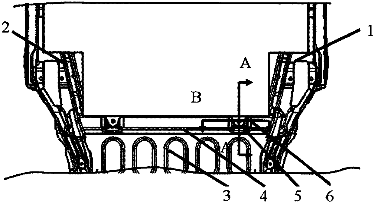
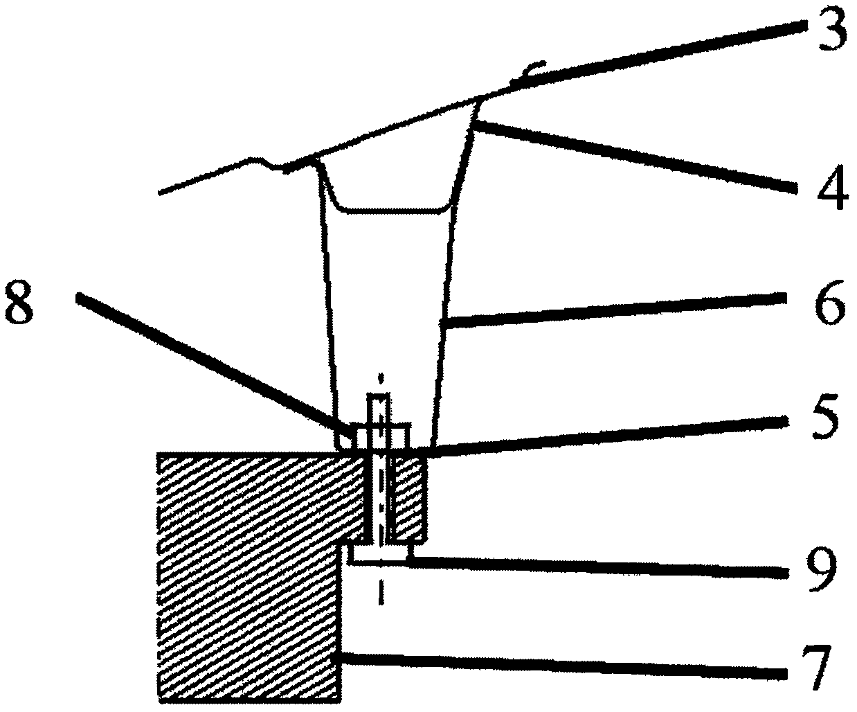
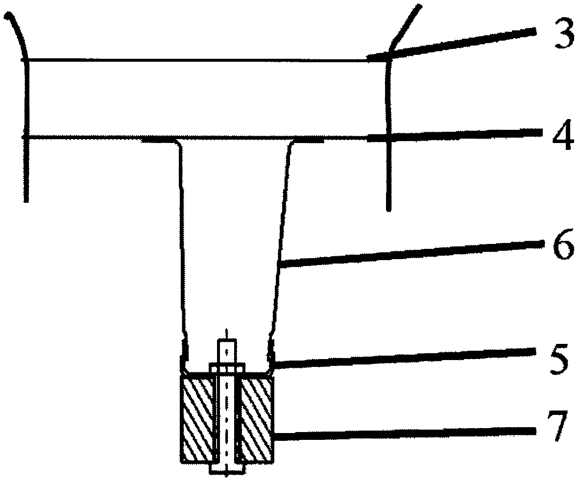
[0024] Such as Figure 1-6 As shown, the power battery installation structure of this embodiment includes a rear floor 3, a left rear longitudinal beam 1 and a right rear longitudinal beam 2 arranged on both sides of the rear floor 3, and a power battery installation plate 6 and a power battery reinforcement plate 5. It also includes a rear underfloor crossbeam 4 arranged under the rear floor 3, the left side of the rear underfloor crossbeam 4 is welded to the left rear longitudinal beam 1, and the right side of the rear underfloor crossbeam 4 is welded to the right rear The longitudinal beam 2 is welded, and the upper surface of the rear floor under-beam 4 is welded with the rear floor 3 and forms a closed cross-sectional structure with the rear floor. The bottoms of the power battery installation plate 6 and the power battery reinforcement plate 5 are welded to the rear floor sub-beam 4 , and the tops of the power battery installation plate 6 and the power battery reinforcem...


PUM


Abstract

The invention relates to a power battery installing structure, and belongs to the technical field of automobile design and manufacturing. The power battery installing structure comprises a rear floor,a left rear longitudinal beam, a right rear longitudinal beam, a power battery installing plate, a power battery reinforcement plate, and a rear floor lower cross beam, wherein the left rear longitudinal beam and the right rear longitudinal beam are arranged on the two sides of the rear floor, and the rear floor lower cross beam is arranged below the rear floor. The left side of the rear floor lower cross beam is welded with the left rear longitudinal beam, the right side of the rear floor lower longitudinal beam is welded with the right rear longitudinal beam, and the upper surface of the rear floor lower cross beam is welded with the rear floor and then forms a closed cross section structure with the rear floor. The bottom of the power battery installing plate and the bottom of the power battery reinforcement plate are welded to the rear floor lower cross beam, and the top of the power battery installing plate and the top of the power battery reinforcement plate are fixedly connected through a bolt and a nut.

Description

technical field [0001] The invention relates to the technical field of automobile design and manufacture, and more specifically, the invention relates to a power battery installation structure. Background technique [0002] With the gradual increase of people's awareness of environmental protection and the support of national industrial policies, electric vehicles are gradually being promoted and applied. In order to ensure a large cruising range, electric vehicles need to install a large number of power batteries. In order to meet the installation reliability of the power batteries, the installation points of the batteries need to meet high strength and rigidity requirements. The designed installation structure must be able to meet the installation requirements of the power battery. Because battery modules are of regular shape, power batteries are generally of regular shape. At the rear of the power battery, affected by the shape of the battery and the suspension of the r...

Claims


Application Information

Patent Timeline
Patent Type & Authority Applications(China)
IPC IPC(8): B62D25/20B60K1/04
CPCB62D25/2027B60K1/04B60K2001/0438
Inventor 张立强
Owner IAT AUTOMOBILE TECH
Learn More