Nitrogen blowing instrument and nitrogen blowing instrument test tube mounting seat
- Summary
- Abstract
- Description
- Claims
- Application Information
AI Technical Summary
Problems solved by technology
Method used
Image
Examples
Embodiment 1
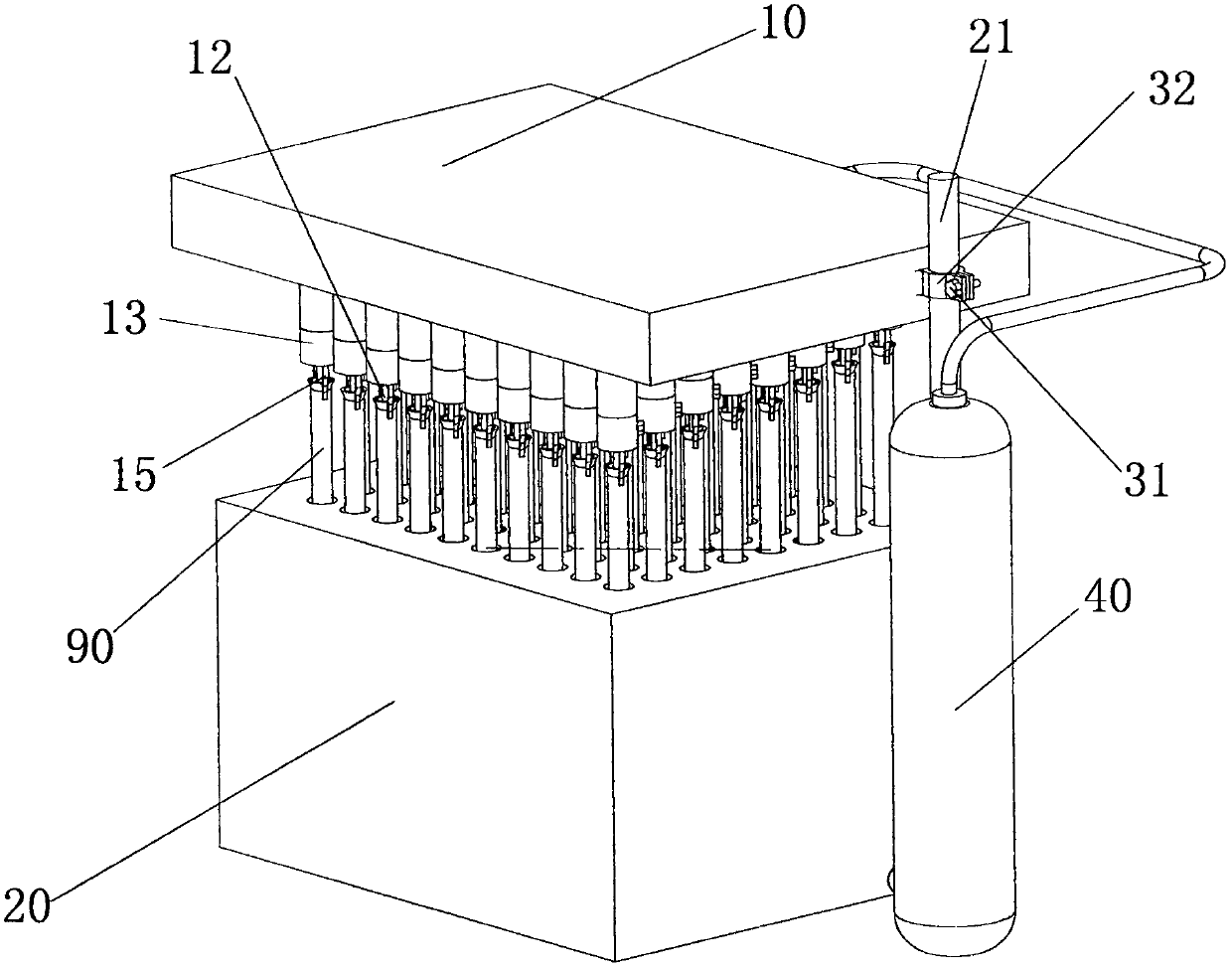
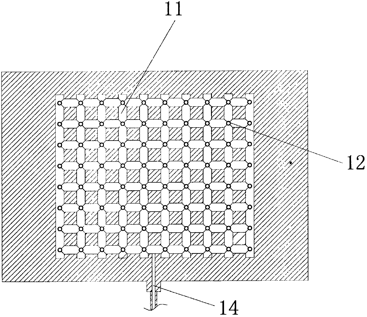
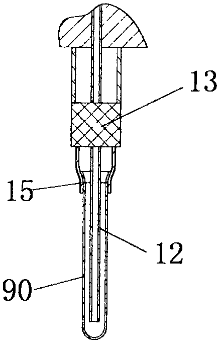
[0039] Such as Figure 1-Figure 2 As shown, the nitrogen blowing instrument includes a base 20 and a test tube mounting base 10, a water bath is provided in the base 20, and the test tube mounting base 10 can be equipped with test tubes 90 in a matrix distribution in a detachable manner, and the test tube mounting base 10 is detachable. Installed on the base 20 in the same way, the test tube mounting base 10 is provided with a ventilation pipeline network 11 inside, and the ventilation pipeline network 11 has an air inlet 14, and the air inlet 14 is used to communicate with the gas source 40, and the ventilation pipeline network 11 is connected with multiple A blowing pipe 12 communicates, and each blowing pipe 12 is used for cleaning a test tube 90, and each blowing pipe 12 is connected with a control valve. Wherein, each test tube mounting seat 10 can be provided with 8*10=80 positions for installing test tubes 90 . The test tube 90 can be installed in the manner of clampin...
Embodiment 2
[0050] Such as image 3 and Figure 4 As shown, the difference between this embodiment and Embodiment 1 is that the air inlet 14 is arranged on the side of the test tube mounting seat 10, and the control valve is a manual control valve 13. As the distance between the blowing pipe 12 and the air inlet 14 increases , the position of the control valve on each blowing pipe 12 gradually decreases.
[0051] By setting the height of the manual valve to be positively or negatively related to the distance from the air inlet 14 of the air blow pipe 12, the characteristics of high air pressure and large air volume of the air blow pipe 12 that is closer to the inlet can be used to dry part of the test tubes 90 first, and can be closed first. This part blows air tube 12, thus concentrates the wind volume of remaining air blowing tube 12 to the air blowing tube 12 that has not yet dried up corresponding test tube 90, to improve the operation efficiency of drying up all test tubes 90 on the...
Embodiment 3
[0059] Such as Figure 5 As shown, the difference between this embodiment and Embodiment 1 is that the air inlet 14 is arranged on the top of the test tube mounting seat 10, the control valve is installed on the top of the test tube mounting seat 10, and the control valve has a hole that can go deep into the blowing pipe 12. The valve core, and the air blowing pipe 12 has different ventilation areas when the valve core is in different positions.
[0060] By installing the air inlet 14 and the control valve on the top of the test tube mounting seat 10, the blowing pipe 12 of the test tube 90 that has been dried earlier can be closed by the operator above, so as to save the air flow, and the remaining air can be applied to the test tube. In the remaining test tube 90 that has not been blown dry, thereby saving the air consumption.
[0061] Specifically, on the outside of each blowing pipe 12, the test tube mount 10 is provided with a test tube 90 clamping device, and the test t...
PUM
 Abstract
Description
Claims
Application Information
 - R&D
- Intellectual Property
- Life Sciences
- Materials
- Tech Scout
- Unparalleled Data Quality
- Higher Quality Content
- 60% Fewer Hallucinations
Browse by: Latest US Patents, China's latest patents, Technical Efficacy Thesaurus, Application Domain, Technology Topic, Popular Technical Reports.
© 2025 PatSnap. All rights reserved.Legal|Privacy policy|Modern Slavery Act Transparency Statement|Sitemap|About US| Contact US: help@patsnap.com


