Insertion frame device with self-locking insertion disc

A self-locking, plug-in technology, applied in the direction of clamping/extracting device, support structure installation, etc., can solve the problems of limited space utilization, inconvenient assembly, and small space occupied by the plug-in panel, so as to increase the effective use of space , Increased business integration and high business integration

Active Publication Date: 2018-05-11
WUHAN TELECOMM DEVICES +1
View PDF4 Cites 4 Cited by
  • Summary
  • Abstract
  • Description
  • Claims
  • Application Information

AI Technical Summary

Problems solved by technology

[0004] In the current existing technical solutions, although the requirements can be met to a certain extent, there are still some defects, which are shown in: 1. Spring screws or ordinary screws that take up less space are used on the plug-in panel, which brings great inconvenience to the assembly. On the other hand, a screwdriver is needed, and the assembly efficiency is low; 2. The plug-in panel is fixed by screws, and the sub-frame needs to reserve an assembly space for the plug-in board and the sub-frame, which cannot be effectively used by the printed circuit board. The optical module cannot be installed, and the space is fully utilized
3. Cancel the handle or reduce the space of the handle. The resulting problems will lead to difficult insertion and removal of the disk, inconvenient maintenance, and poor user experience.
If the device is not designed as a pluggable plug-in structure, the space can be fully utilized, but it involves dismantling the device for follow-up maintenance, which will greatly affect the normal work, and it is difficult for customers to accept

Method used


Image

  • Insertion frame device with self-locking insertion disc
  • Insertion frame device with self-locking insertion disc
  • Insertion frame device with self-locking insertion disc

Examples


Embodiment

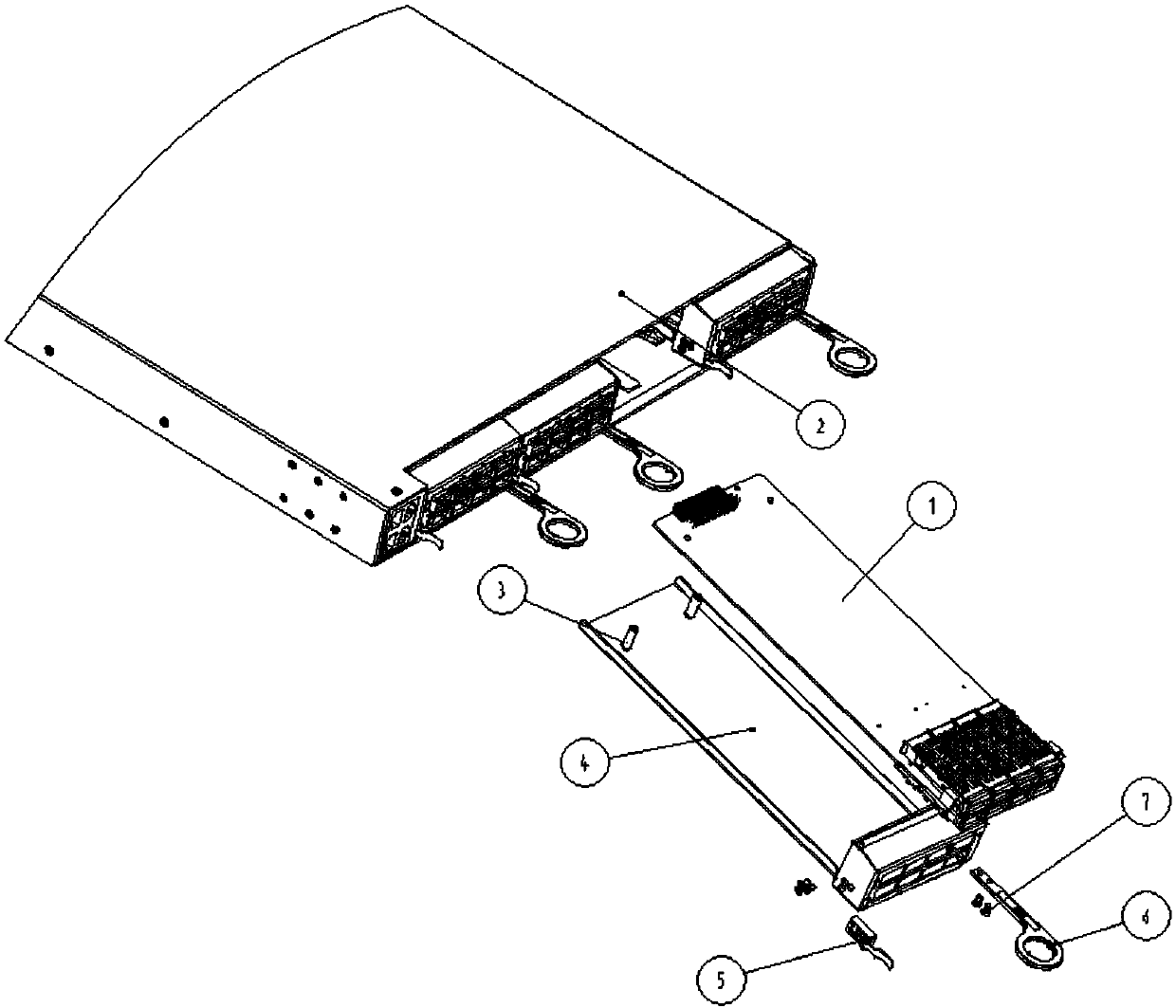
[0050] One, at first introduce the device structure of the present invention.

[0051] Such as figure 1 As shown, the frame structure with a self-locking insert consists of a printed circuit board 1, an insert frame 2, a riveting stud 3, an insert frame 4, a buckle assembly workpiece 5, a handle 6 and a countersunk screw 7 composition. The self-locking plug-in structure is composed of a printed circuit board 1, a pressure riveting stud 3, a plug-in frame 4, a buckle assembly workpiece 5, a handle 6 and a countersunk screw 7. The printed circuit board 1 is fixed on the outer frame 4 of the plug-in disk through the riveting stud 3 , and the snap-fit ​​assembly workpiece 5 and the handle 6 are fixed on the outer frame 4 of the plug-in disk through the countersunk head screw 7 . The printed circuit board 1 is provided with an optical module at the plug panel, and an electrical connector is provided at the end. The self-locking plug-in plate structure is connected with the plug-...


PUM


Abstract

The invention relates to an insertion frame device with a self-locking insertion disc. The insertion frame device comprises an insertion card, wherein a clamping seat assembly structure and a flat handle are arranged on the insertion card, a clamping seat assembly is arranged on a side surface of the insertion card, the flat handle is arranged on the other side surface of the insertion card and isparallel to a bottom surface of the insertion card, a spherical bulge is arranged at the top of the insertion card and is provided with a compensation gap, a clamping seat, a handle, a floating blockand a spring are arranged on the clamping seat assembly, the handle can rotate around a rotation shaft arranged on the clamping seat within a certain amplitude range, an insertion card slot is formedin each insertion card slot position at the bottom of the insertion frame and is used for limiting an assembly correction position of the insertion card, a folded edge is arranged at a front end of the bottom of the insertion frame, insertion of the insertion card is facilitated, the locking reliability is improved, and guide rails are arranged at two sides of an internal slot position of the insertion frame and are used for guiding the insertion card to slide. The insertion frame has the advantages of high service integration, high assembly efficiency and reliable locking performance, the space of an equipment panel can be fully utilized, and the defect in the existing scheme is overcome.

Description

technical field [0001] The invention relates to a frame insertion device, in particular to a frame insertion device with a self-locking insertion disk. Background technique [0002] With the continuous evolution of communication technology and the rapid development of data services, in the "Internet +" era, whether it is convergence, network, or storage, new requirements are put forward for communication networks, equipment, and terminals. The turbulent "Internet +" era is forcing the communication industry to usher in a new round of changes, pushing it to develop in the direction of mobility, intelligence and high integration. As far as communication equipment is concerned, it is extremely important to place the number of optical modules used for transmission or access in the same volume of equipment panel space. Most of these equipment panels require the use of multiple separate, flexible plug-in structures. How to make full use of the equipment panel space is an urgent p...

Claims


Application Information

Patent Timeline
IPC IPC(8): H05K7/14
CPCH05K7/1402
Inventor 关卫林徐健胡文娟喻杰奎全本庆罗清
Owner WUHAN TELECOMM DEVICES
Why Eureka
Try Eureka