
Device for depositing sliver in can

A technology of fiber slivers and equipment, applied in the field of equipment for storing fiber slivers into cans, can solve problems such as difficult to achieve and time-consuming

Active Publication Date: 2018-05-11
TRUETZSCHLER GRP SE
View PDF8 Cites 0 Cited by
  • Summary
  • Abstract
  • Description
  • Claims
  • Application Information

AI Technical Summary

Problems solved by technology

This is time-consuming and difficult for the operator to realize especially for large cans at a height of about 1.60 to 1.80 meters at an unfavorable position

Method used


Image

  • Device for depositing sliver in can
  • Device for depositing sliver in can
  • Device for depositing sliver in can

Examples


Embodiment Construction

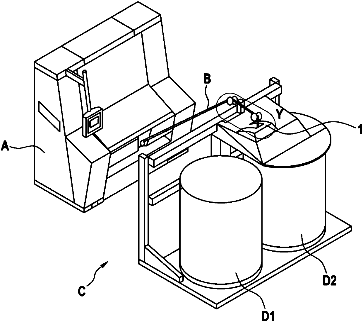
[0021] figure 1 A card A is shown, from which the fiber slivers B are guided via the coiling head 1 into the can changer C and deposited in the cans D1 , D2 . In this exemplary embodiment, the can changer C is designed as a linear can changer, in which the coiling head 1 is arranged so that it can move linearly along the frame or the frame wall.

[0022] However, the can changer C can also be designed as a rotating can changer, wherein the cans D1 , D2 are changed by means of a rotating device below the stationary coil head 1 . In this exemplary embodiment, the coil head 1 is arranged below a housing which is not shown in detail and is described in detail in the following figures.

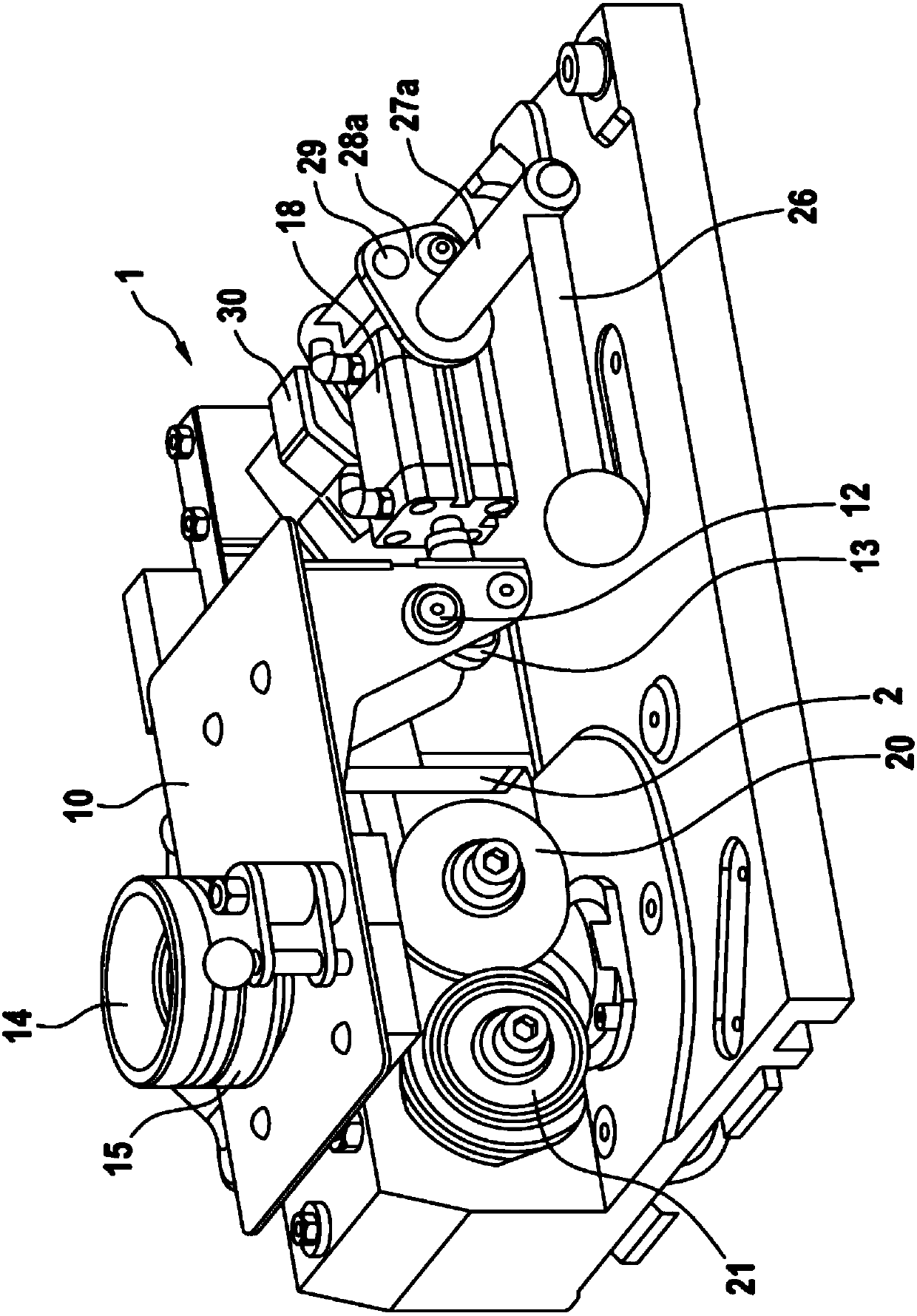
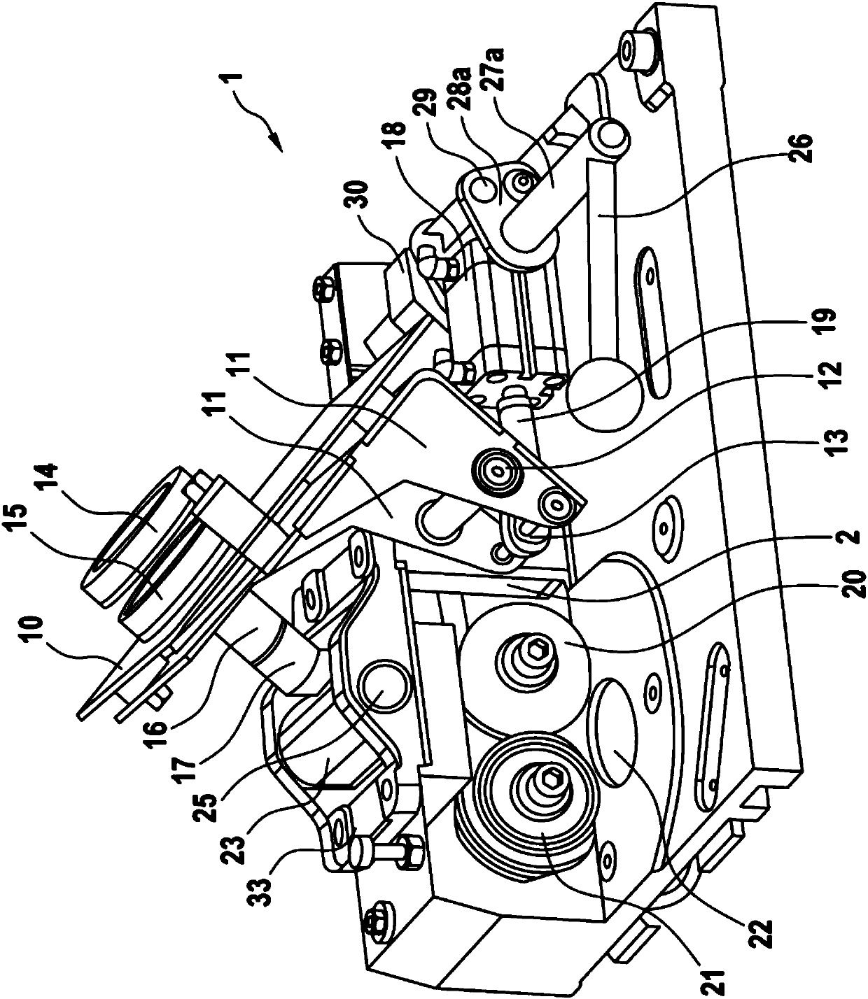
[0023] figure 2 The coil head 1 is shown in the ready-to-run position. Mainly the previous section funnel 16 and the fiber strip funnel 17 arranged below it (see image 3 ) and traction rollers 20,21. The fiber sliver is guided, for example, from the card to the coil head 1 of the can changer...


PUM


Abstract

The invention relates to a device (C) for depositing a sliver (B) in a can, comprising a depositing head (1) having pull-off rollers (20, 21) for transporting the sliver across a rotatable turntable arranged below the depositing head (1) into the can (D1, D2) and comprising at least one pivotably arranged sliver funnel (17) for automatically cutting the sliver when the can is exchanged. The invention is characterized in that the device has means by means of which the distance between the pull-off rollers (20, 21) can be enlarged and by means of which at least the sliver funnel (17) can be moved away from the pull-off rollers (20, 21).

Description

technical field [0001] The invention relates to a device for depositing fiber slivers into cans, the device having a coiling head with a device for transporting the fiber slivers into the cans via a rotatable turntable arranged below the coiling head and has at least one swivel-arranged sliver funnel for automatically breaking the sliver when changing cans. Background technique [0002] In the known state of the art, the fiber slivers provided by the spinning preparation machines are taken up by so-called coilers. The sliver is conveyed via the sliver hopper to the calender roll pair with the aid of a guide, which deposits the sliver via the turntable into the can already erected. If the can is full, the fiber sliver is broken, wherein at the same time the full can is removed and the empty can is replenished. [0003] A coiling head of a can changer is described in DE 3807239 A1, in which the sliver from the card is guided into the sliver hopper and is guided to the rotati...

Claims


Application Information

Patent Timeline
Patent Type & Authority Applications(China)
IPC IPC(8): D01H9/02B65H54/80D01G15/46
CPCB65H54/80D01H5/72D01H9/02D01G15/46B65H2701/311
Inventor 马库斯·施密茨
Owner TRUETZSCHLER GRP SE
Learn More