A stainless steel wire variable diameter processing equipment and its working process
A technology of stainless steel wire and processing equipment, which is applied in the field of stainless steel wire variable diameter processing equipment and its work flow, and can solve the problems that the cutting equipment cannot cut well, does not have straightening function, and the clamping degree of stainless steel wire is poor.
Inactive Publication Date: 2019-10-01
唐山市古冶区汉川金属制品有限公司
View PDF7 Cites 0 Cited by
- Summary
- Abstract
- Description
- Claims
- Application Information
AI Technical Summary
Problems solved by technology
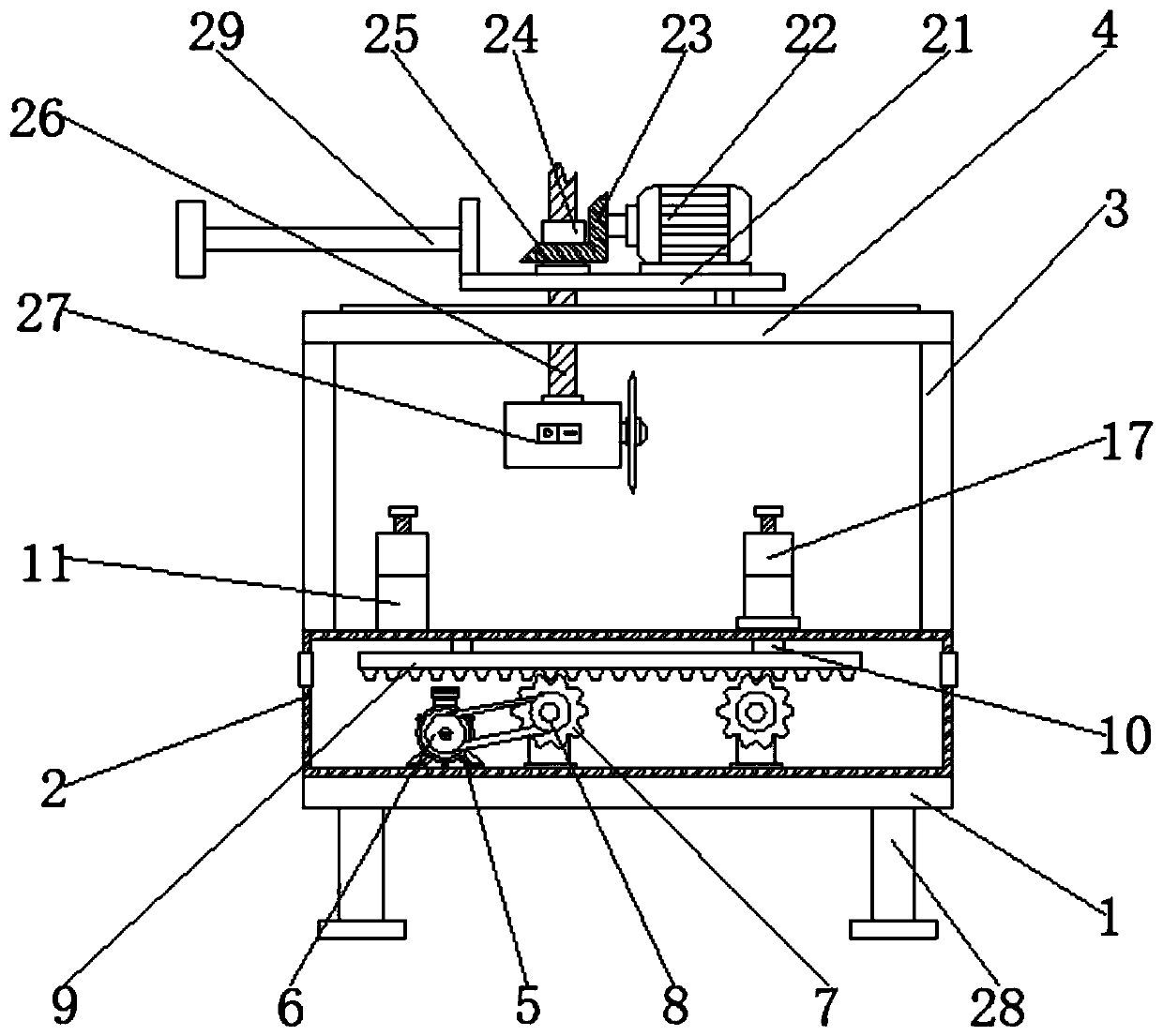
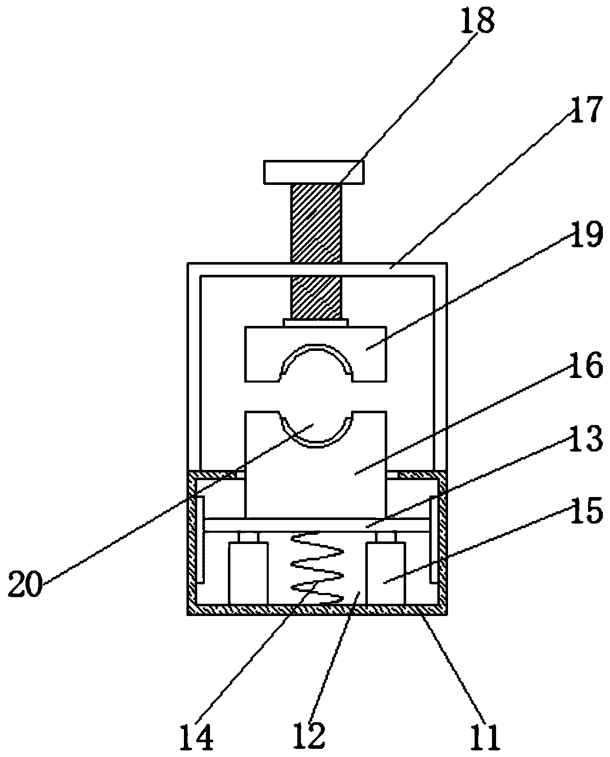
Aiming at the deficiencies of the prior art, the present invention provides a stainless steel wire variable-diameter processing equipment and its working process, which solves the problem that the existing device has a very poor clamping degree on the stainless steel wire and does not have the function of straightening, which leads to cutting The problem that the equipment can not cut well
Method used
View moreImage
Smart ImageViewing Examples
Examples
Embodiment Construction
Login to View More PUM
 Abstract
The invention discloses stainless-steel-wire reducing machining equipment and work flow thereof and relates to the technical field of stainless steel reducing machining equipment. The stainless-steel-wire reducing machining equipment comprises a bottom plate and is characterized in that a box is fixedly connected to the top of the bottom plate, fixed blocks are fixedly connected to two sides of the top of the box, a fixed plate is fixedly connected between the tops of the two fixed blocks, a first motor is fixedly connected to the bottom of the inner wall of the box, a first belt pulley sleeves the outer surface of the output shaft of the first motor, a first gear is rotatably connected to the bottom, located on the first motor side, of the inner wall of the box through a support rod, a second belt pulley is fixedly connected to the front side of the first gear, and the outer surface of the second belt pulley is in transmission connection with the outer surface of the first belt pulleythrough a belt. The stainless-steel-wire reducing machining equipment and the work flow thereof have the advantages that the equipment is quite good in clamping effect and has a good clamping and straightening function, cutting equipment can well cut stainless steel wires, and equipment flexibility is increased.
Description
technical field The invention relates to the technical field of stainless steel diameter-reducing processing equipment, in particular to stainless steel wire diameter-reducing processing equipment and its working process. Background technique Stainless steel wire, also known as stainless steel wire, is a variety of silk products of different specifications and models made of stainless steel. The cross section of stainless steel wire is generally round or flat. The common stainless steel wire with good corrosion resistance and high cost performance is 304 And 316 stainless steel wire, stainless steel wire drawing pulls the wire rod or wire blank from the die hole of the wire drawing die under the action of the drawing force to produce small-section steel wire or non-ferrous metal wire. Metal wires of different cross-sectional shapes and sizes of various metals and alloys can be produced by drawing. The drawn wires have precise dimensions and smooth surfaces, and the drawing e...
Claims
Login to View More Application Information
Patent Timeline
 Patent Type & Authority Patents(China)
IPC IPC(8): B21F1/02B21F11/00
Inventor 卢燕平
Owner 唐山市古冶区汉川金属制品有限公司
Features
- R&D
- Intellectual Property
- Life Sciences
- Materials
- Tech Scout
- Unparalleled Data Quality
- Higher Quality Content
- 60% Fewer Hallucinations
Learn More Browse by: Latest US Patents, China's latest patents, Technical Efficacy Thesaurus, Application Domain, Technology Topic, Popular Technical Reports.
© 2025 PatSnap. All rights reserved.Legal|Privacy policy|Modern Slavery Act Transparency Statement|Sitemap|About US| Contact US: help@patsnap.com


