Wheel set withdrawing machine provided with clamping key structure wheel withdrawing seat capable of being used bi-directionally

A technology for removing wheel seats and unloading machines, which is applied in metal processing, metal processing equipment, manufacturing tools, etc., can solve the problems of elasticity and deformation of wheelsets that cannot be removed from brake discs, and achieve reasonable structure, high strength, good workmanship effect

Active Publication Date: 2018-05-15
李立群
View PDF6 Cites 0 Cited by
  • Summary
  • Abstract
  • Description
  • Claims
  • Application Information

AI Technical Summary

Problems solved by technology

[0006] The technical problem to be solved by the present invention is to provide a wheel set unloading machine with a two-way use card key structure unloading seat, which solves the problem that the traditional wheel set unloading machine cannot unload the wheel set with the brake disc. The defect of elastic deformation due to the concentration of load at the bearing jaw

Method used


Image

  • Wheel set withdrawing machine provided with clamping key structure wheel withdrawing seat capable of being used bi-directionally
  • Wheel set withdrawing machine provided with clamping key structure wheel withdrawing seat capable of being used bi-directionally
  • Wheel set withdrawing machine provided with clamping key structure wheel withdrawing seat capable of being used bi-directionally

Examples


Embodiment Construction

[0027] In order to make the technical means, creative features, goals and effects achieved by the present invention easy to understand, the present invention will be further described below in conjunction with specific illustrations.

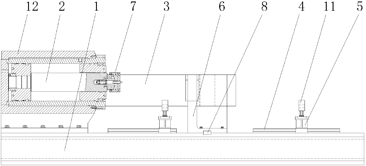
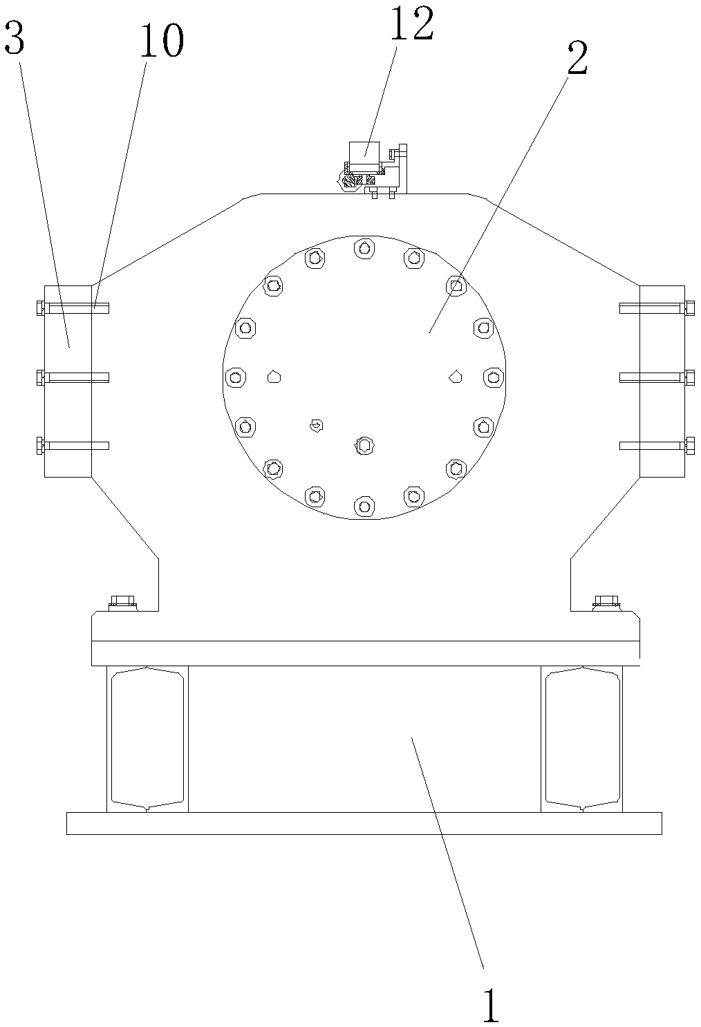
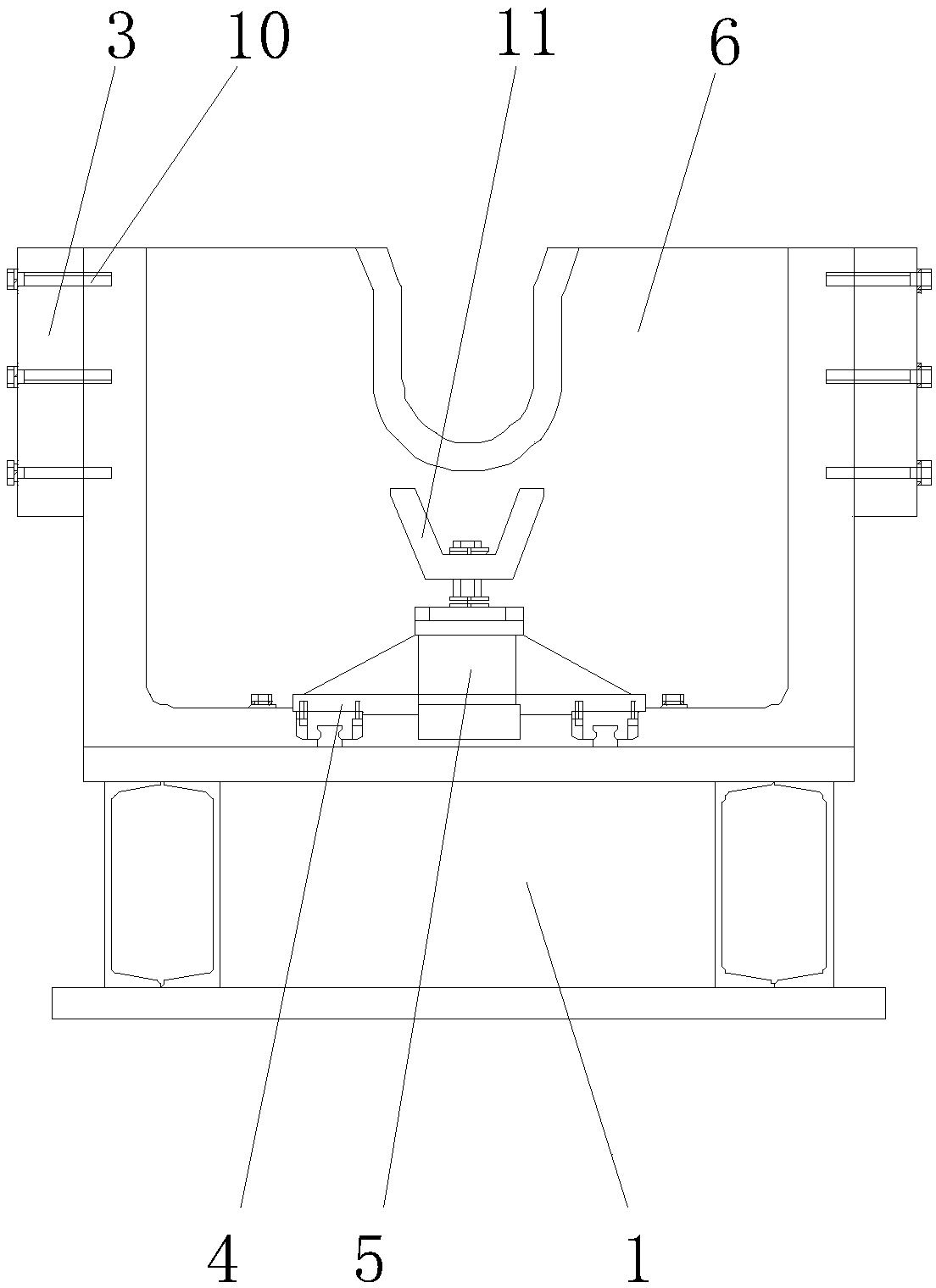
[0028] to combine Figure 1 to Figure 4 As shown, a wheel set unloading machine with a two-way use card key structure unloading seat, including base 1, unloading hydraulic cylinder 2, side pull plate 3, linear track 4, jacking cylinder 5 and unloading seat 6. The unloading hydraulic cylinder 2 is set at one end of the base 1, the output end of the unloading hydraulic cylinder 2 is provided with a flexible top 7, and there are two side pull plates 3, which are respectively set on both sides of the base 1, and the pulley seat 6 is located in the middle of the base 1, and two side pull plates 3 fixedly connect the unloading hydraulic cylinder 2 and the unloading wheel base 6 from both sides. The linear track 4 is divided into two groups, and the tw...


PUM


Abstract

The invention discloses a wheel set withdrawing machine provided with a clamping key structure wheel withdrawing seat capable of being used bi-directionally. The wheel set withdrawing machine comprises a base, a withdrawing hydraulic cylinder, two side pulling plates, two linear rails, two jacking air cylinders and the wheel withdrawing seat; the withdrawing hydraulic cylinder is arranged at one end of the base; a flexible ejecting head is arranged at the output end of the withdrawing hydraulic cylinder; the wheel withdrawing seat is arranged in the middle of the base; the withdrawing hydraulic cylinder and the wheel withdrawing seat are fixedly connected together by the aid of the two side pulling plates from two sides; the two linear rails are separately arranged on two sides of the wheel withdrawing seat; and the two jacking air cylinders are movably arranged on the linear rails correspondingly. The wheel set withdrawing machine has the advantages that the provided wheel withdrawingseat is reasonable in structure, good in manufacturability and high in strength, the stable and effective use condition of the large withdrawing force up to hundreds of tons during wheel withdrawingcan be met, the requirement for withdrawing of a brake disc provided with two or three brake disc wheel sets can also be met through adjustment of the direction of the wheel withdrawing seat, and thusthe operations of wheel withdrawing and brake disc withdrawing are realized reliably.

Description

technical field [0001] The invention relates to the field of wheel set dismantling equipment, in particular to a wheel set unloading machine with a two-way usable key structure wheel unloading seat. Background technique [0002] Wheel sets for railway vehicles are usually divided into two categories: wheel sets for passenger cars and wheel sets for freight cars. The main difference between the two is that the wheel sets for freight cars are not equipped with brake discs. Seat position, and the wheel set for passenger cars must also be press-fitted with two or three sets of brake discs in the second wheel gear. When the wheelset is unloading, the wheel unloading force is very large, some can reach more than 400 tons, and the brake disc can usually be withdrawn by tens of tons. [0003] The main problems that exist in the existing wheel-removing equipment have the following two points: [0004] First, the existing wheel-removing machine with fixed wheel-removing seat can onl...

Claims


Application Information

Patent Timeline
Patent Type & Authority Applications(China)
IPC IPC(8): B23P19/027
CPCB23P19/027
Inventor 李立群
Owner 李立群
Why Eureka
Try Eureka