Cable guide self-adjusting device

A self-adjusting, cable technology, used in transportation and packaging, conveying filamentous materials, thin material handling, etc., can solve the problems of inconvenient operation, low device service life, wear of guide pulley mounting brackets, etc., and achieve easy installation or removal. , Improve the service life, the effect of fast fixing

Pending Publication Date: 2018-05-15
HEILONGJIANG LANDE ULTRASONIC TECH CO LTD
View PDF0 Cites 11 Cited by
  • Summary
  • Abstract
  • Description
  • Claims
  • Application Information

AI Technical Summary

Problems solved by technology

The guide pulley used in the past is set at the wellhead through a fixed connection, and the guide angle cannot be adjusted according to the needs; a few cable guide devices with rotation function, the guide pulley mounting frame wears seriously when rotating during the working process, and the service life of the device is low. Moreover, the fixing operation of the cables on the guide wheels is cumbersome and inconvenient to operate

Method used


Image

  • Cable guide self-adjusting device
  • Cable guide self-adjusting device
  • Cable guide self-adjusting device

Examples


specific Embodiment approach 1

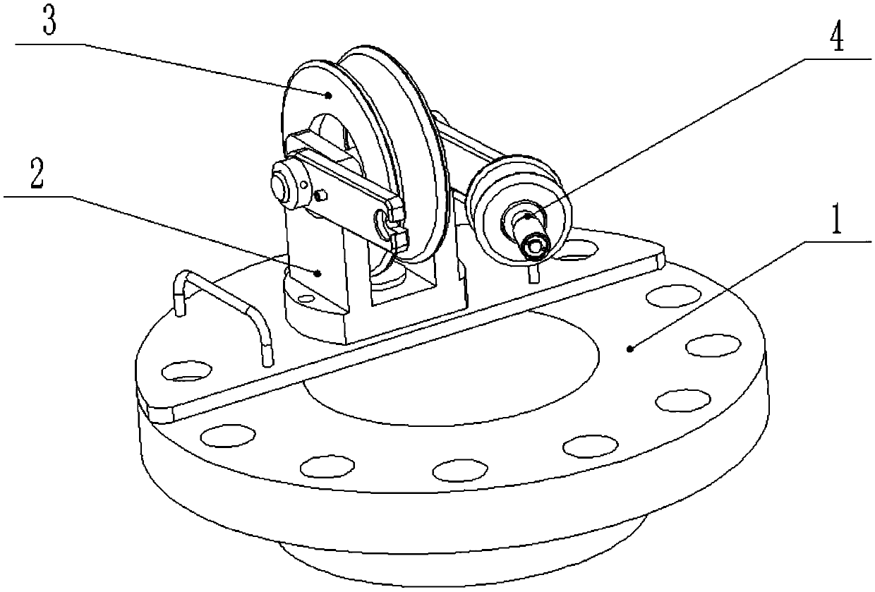
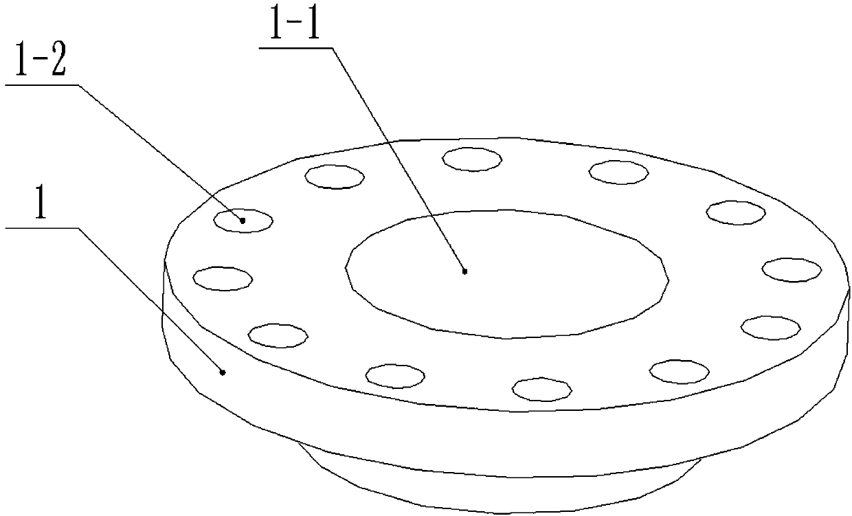
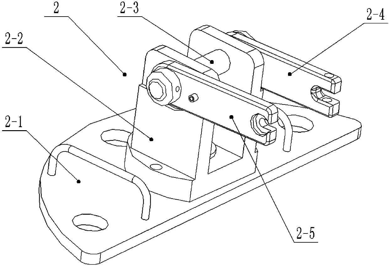
[0033] Combine below Figure 1-13 Describe this embodiment, a cable guide self-adjusting device, including a flange plate 1, a rotating base 2, a pulley 3 and an auxiliary wheel assembly 4, the rotating base 2 is fixedly connected to the upper end of the flange plate 1, and the pulley 3 Rotationally connected to the upper end of the rotating base 2, one end of the auxiliary wheel assembly 4 is hinged to the rotating base 2, and the other end of the auxiliary wheel assembly 4 is clamped on the rotating base 2; the rotating base 2 includes a base 2-1 , a swivel frame 2-2, an upper shaft 2-3, a support arm I2-4 and a support arm II2-5, the swivel frame 2-2 is rotatably connected to the upper end of the base 2-1, and the base 2-1 is fixedly connected On the flange 1, the upper rotating shaft 2-3 is rotatably connected to the upper end of the rotating frame 2-2, the pulley 3 is rotatably connected to the upper rotating shaft 2-3, the supporting arm I2-4 and the supporting arm II2 ...

specific Embodiment approach 2

[0034] Combine below Figure 1-13 Describe this embodiment, this embodiment will further explain the first embodiment, the rotating base 2 also includes a lower rotating sleeve 2-6, an upper rotating sleeve 2-7 and a positioning bolt 2-8, and the lower rotating sleeve 2-6 The clearance fit is on the lower end of the rotating frame 2-2, the upper rotating sleeve 2-7 is clearance fitting on the upper end of the rotating frame 2-2, and the positioning bolts 2-8 pass through the upper rotating sleeve 2-7 sequentially from top to bottom and the lower rotating sleeve 2-6, the lower end of the positioning bolt 2-8 is threadedly connected to the base 2-1, when the rotating base 2 rotates, the lower rotating sleeve 2-6 contacts the upper rotating sleeve 2-7 to generate friction, and the The lower rotating sleeve 2-6 and the upper rotating sleeve 2-7 are made of wear-resistant materials, which can effectively prevent the friction loss when the rotating base 2 rotates, and improve the se...

specific Embodiment approach 3

[0035] Combine below Figure 1-13 Describe this embodiment, this embodiment will further explain Embodiment 2, there is a gap between the lower end surface of the rotating frame 2-2 and the upper end surface of the base 2-1, the gap is greater than 0.5mm, the rotating frame 2-2 Without being in contact with the base 2-1, when the rotating frame 2-2 rotates relative to the base 2-1, there will be no friction loss between the rotating frame 2-2 and the base 2-1.


PUM


Abstract

The invention relates to a cable guide device, in particular to a cable guide self-adjusting device. The cable guide self-adjusting device comprises a flange plate, a rotating base, a pulley and an auxiliary wheel module; the rotating base is fixedly connected to the upper end of the flange plate; the pulley is in transmission connection to the upper end of the rotating base; and one end of the auxiliary wheel module is hinged with the rotating base, and the other end of the auxiliary wheel module is clamped on the rotating base. The cable guide self-adjusting device has the following beneficial effects: cables can be guided, and the guide angle can be rotationally adjusted; the loss caused by contact friction between the base and the rotating frame can be effectively prevented, and the service life of the device is prolonged; and the cables can be quickly fixed to achieve the advantage of convenience to install or disassemble.

Description

technical field [0001] The invention relates to a cable guiding device, more specifically a cable guiding self-adjusting device. Background technique [0002] During the oil drilling process, the cable needs to go deep underground with the drilling equipment. Due to the small wellhead, it is often necessary to use guiding equipment to guide the cable during the special exploration process to avoid friction and collision between the cable and the well wall. The guide pulley used in the past is set at the wellhead through a fixed connection, and the guide angle cannot be adjusted according to the needs; a few cable guide devices with rotation function, the guide pulley mounting bracket wears seriously when rotating during the working process, and the service life of the device is low. And the fixed operation of cable on guide wheel is loaded down with trivial details, and operation is inconvenient. Contents of the invention [0003] The purpose of the present invention is t...

Claims


Application Information

Patent Timeline
Patent Type & Authority Applications(China)
IPC IPC(8): B65H57/14
CPCB65H57/14B65H2701/34
Inventor 赵宪忠高曼琦任建军任耀军孙科林姚望
Owner HEILONGJIANG LANDE ULTRASONIC TECH CO LTD
Why Eureka
Try Eureka