
Detection system and mixer

A technology of detection system and detection circuit, which is applied in the direction of radio wave measurement system, measurement device, geophysical measurement, etc., and can solve problems such as user safety hazards, stirring tool displacement, and affecting product use effects

Pending Publication Date: 2018-05-15
宁波拓邦智能控制有限公司
View PDF6 Cites 2 Cited by
  • Summary
  • Abstract
  • Description
  • Claims
  • Application Information

AI Technical Summary

Problems solved by technology

[0004] The invention provides a detection system, aiming to solve the problems in the prior art that the mixing tool of the mixing product is displaced and damaged, which affects the use effect of the product, and if the tool breaks, it will bring safety hazards to the user

Method used


Image

  • Detection system and mixer
  • Detection system and mixer
  • Detection system and mixer

Examples


Embodiment 1

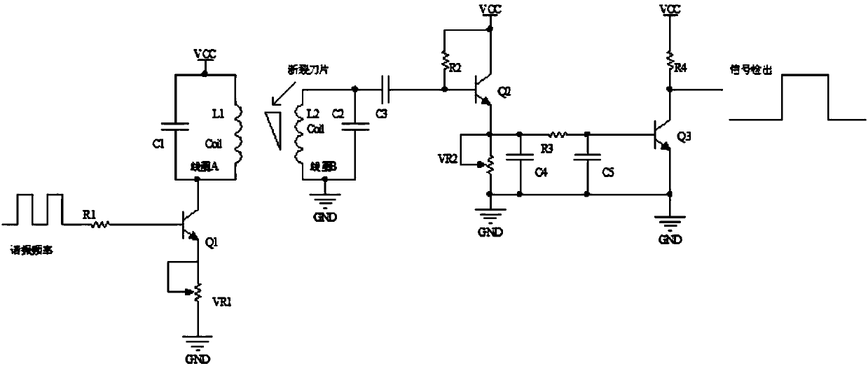
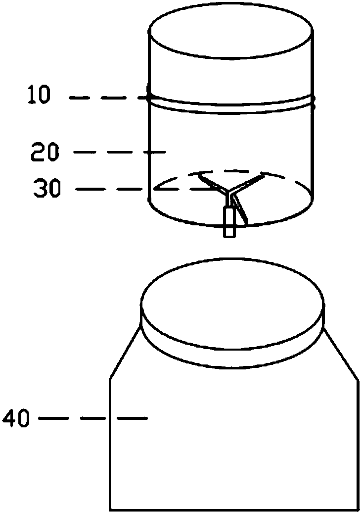
[0038] figure 1 It is a detection system provided by the embodiment of the present invention. The detection system is applied to stirring products. The above-mentioned stirring products should include a knife 30 for stirring operation; the detection system includes an induction device and a detection circuit. In an example, the induction device includes at least one induction coil 10, and the induction coil 10 is connected with the detection circuit. When the detection circuit is energized, the induction coil 10 is energized to generate an induced magnetic field. Within a stable numerical range, the normal operation of the cutter 30 mentioned here should be that the installation position of the cutter 30 has not changed, and the cutter 30 itself has no deformation and damage. In the embodiment of the present invention, when the cutting tool 30 is working normally, the induction coil 10 will output a normal working signal to the detection circuit, and the detection circuit will...

Embodiment 2

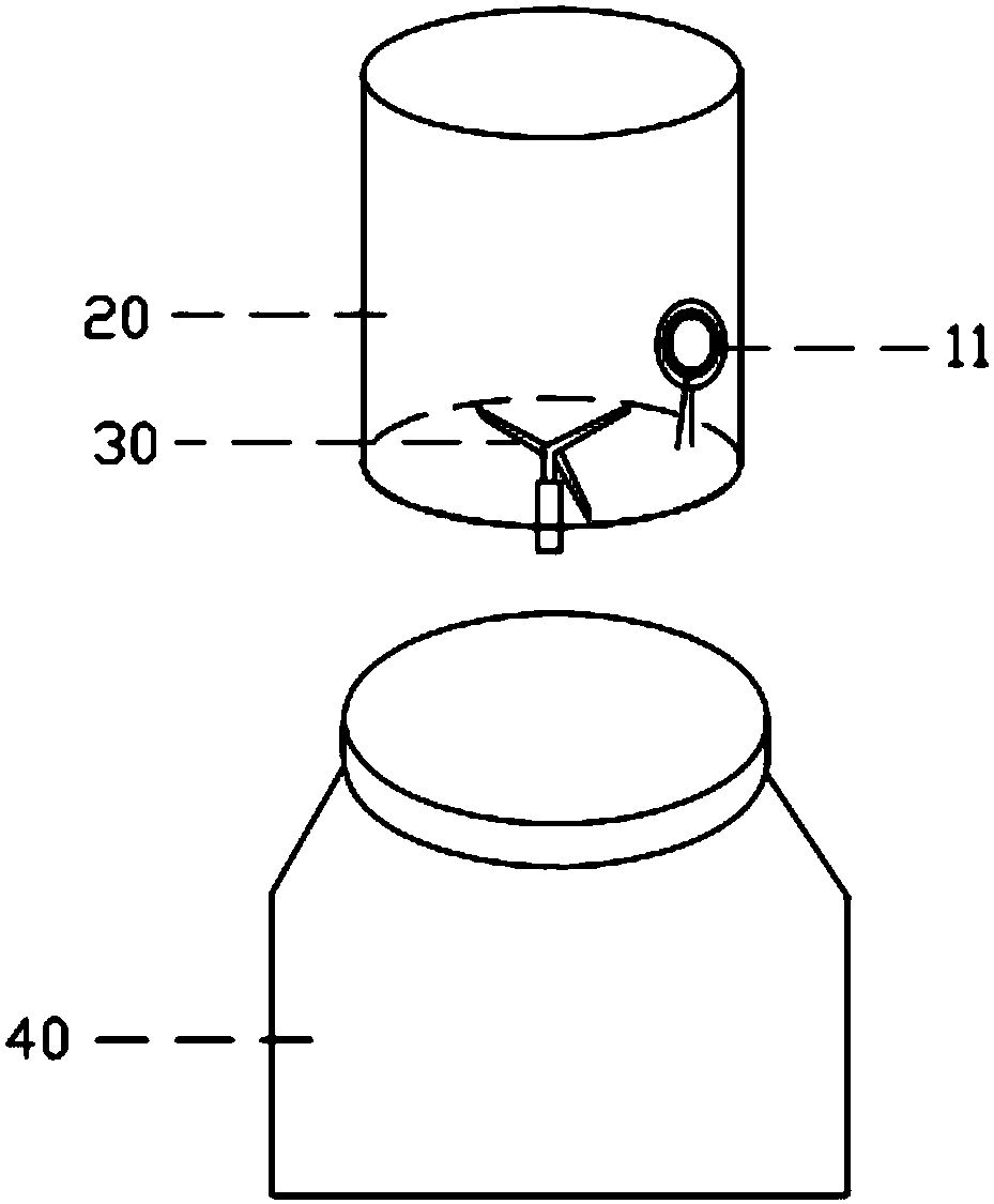
[0044] The detection system provided in the embodiment of the present invention is applied to stirring products. The difference between it and Embodiment 1 is that the stirring product includes a cup body 20. It should be understood that the cup body 20 is a container for holding objects to be stirred. Its own shape, material, etc. are not limited in any way. In the embodiment of the present invention, the induction device includes at least one induction coil 10 , and the induction coil 10 is wound on the above-mentioned cup body 20 .

[0045] In the embodiment of the present invention, the winding position of the induction coil 10 can be the inner wall, the outer wall or the bottom of the cup body 20. In a preferred embodiment, the induction coil 10 is arranged on the cup body for safety or cleaning convenience. 20 of the outer wall. Wherein, the winding manner of the induction coil 10 may be to surround the entire cup body 20, or may be wound sideways at any position on the...

Embodiment 3

[0058] An embodiment of the present invention provides a blender, including a cutter 30 , a cup body 20 , a base 40 ; and any detection system as described in Embodiments 1-2, which will not be repeated here.


PUM


Abstract

The invention belongs to the electrical appliance field and provides a detection system. The detection system is applied to a stirring-class product with a stirring cutter; the detection system comprises an induction device and a detection circuit; the induction device can generate an inducted magnetic field; the parameters of the induced magnetic field are in a stable numerical value range when the cutter works normally; the working state of the cutter changes when the cutter displaces, deforms, or even is fractured, and the parameters of the induced magnetic field also change; induction signals are outputted to the detection circuit; the detection circuit processes the induction signals and outputs detection signals, wherein the detection signals reflect the current working state of thecutter; and when the signals are inconsistent with a preset signal state which appears when the cutter works normally, it can be accurately judged that an abnormality occurs on the cutter, and a usercan perform subsequent processing. With the detection system adopted, the user know the abnormality of the cutter immediately when the cutter is working abnormally, and therefore, follow-up use is notaffected, and potential safety hazards can be effectively avoided.

Description

technical field [0001] The invention belongs to the field of electrical appliances, in particular to a detection system and a mixer. Background technique [0002] Stirring products, such as blenders and kitchen machines, are popular and widely used because of their convenient and fast functional characteristics. [0003] The stirring products are all equipped with stirring knives according to their functions. In the existing technology, due to the influence of various factors such as the quality of the knives, the manufacturing process of the product, and the service life, the installation position of the knives will move, the knives will be deformed, or the knives will be damaged. If it is damaged, it will affect the use effect of stirring products; in more serious cases, if the stirring tool breaks, it is mixed in the stirred food and poured out together with the food, which will endanger the user's safety when eating, especially When the broken part of the knife is small...

Claims


Application Information

Patent Timeline
Patent Type & Authority Applications(China)
IPC IPC(8): G01V3/11A47J43/07
CPCA47J43/075G01V3/10
Inventor 蔡传斌
Owner 宁波拓邦智能控制有限公司
Learn More