Copper bar connecting structure production method

A connection structure, copper bar technology, applied in the direction of clamping/spring connection, contact parts, etc., can solve the problems of current flow line changes, time-consuming and labor-intensive, etc., to achieve fast heat dissipation, economic benefits, and large heat dissipation area. Effect

Inactive Publication Date: 2018-05-15
黄样忠
View PDF0 Cites 0 Cited by
  • Summary
  • Abstract
  • Description
  • Claims
  • Application Information

AI Technical Summary

Problems solved by technology

[0003] According to the change of the current and the number of input lines, drill holes and install bolts on the power input copper bars to fix the output copper bars. This connection method is time-consuming and labor-intensive, and the current flow lines on the input copper bars after drilling will also change

Method used


Image

  • Copper bar connecting structure production method
  • Copper bar connecting structure production method
  • Copper bar connecting structure production method

Examples


Embodiment Construction

[0013] Below in conjunction with accompanying drawing and specific embodiment the present invention is described in further detail:

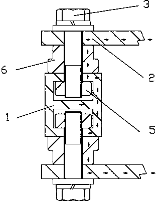
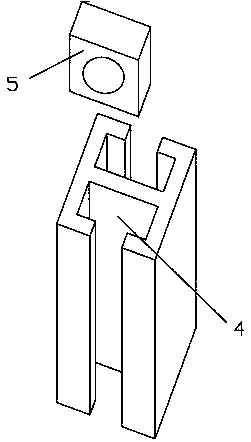
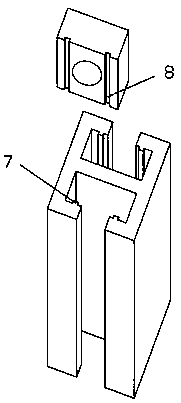
[0014] As shown in Figure 1 to Figure 3, the copper bar connection structure includes input copper bar 1, output copper bar 2 and bolt 3, the input copper bar and output copper bar are set in a cross, and the cross section of the input copper bar is "I" , there are long grooves 4 on both sides, and nuts 5 are arranged in the long grooves. The nuts can be hexagonal nuts or square nuts. The nuts can be moved to a designated position to fix the output copper bar without drilling and will not change the flow trace of the current. The surface of the nut on the side that is against the input copper bar is flat, which can increase the contact area. A conductive pad 6 is set between the input copper bar and the output copper bar. The upper and lower surfaces of the conductive pad are flat, and the bolts pass through the output in turn. After the copper ...


PUM


Abstract

The invention discloses a copper bar connecting structure comprising an input copper bar, an output copper bar and a bolt, wherein the input copper bar and the output copper bar are arranged in a crossed manner, the cross section of the input copper bar is in an I shape, long grooves are formed in the two sides of the input copper bar, and nuts are arranged in the long grooves, a conductive cushion block is arranged between the input copper bar and the output copper bar, the bolt penetrates through the output copper bar and the conductive cushion block in sequence, and then is fixed on the nuts in the long grooves, the cross section of each long groove is in a convex shape, a convex strip is arranged on the inner surface of the opening end of the long groove, and a groove is formed in thesingle side surface of each nut, and the convex strip is clamped into the groove. The method has the advantages that the input copper bar is designed into an I shape, the nuts can slide in the long grooves, so that the output copper bar can be fixed at any position in the long grooves, hole punching is not needed, the current flows from the input copper bar, passes through the conductive cushion block and then flows out of the output copper bar.

Description

technical field [0001] The invention relates to a connection structure, in particular to a copper bar connection structure. Background technique [0002] There will be many distribution cabinets in a substation. The copper bars in the existing power distribution cabinets are flat and long. The wider copper bars are the power input copper bars, and the thinner copper bars are the power supply bars. Output copper bar, a relatively large copper bar will arrange multiple parallel output copper bars. [0003] According to the change of the current and the number of input lines, drill holes and install bolts on the power input copper bars to fix the output copper bars. This connection method is time-consuming and labor-intensive, and the current flow lines on the input copper bars after drilling will also change. Contents of the invention [0004] The invention aims at the deficiencies of the prior art, and provides a copper bar connection structure that can be directly instal...

Claims


Application Information

Patent Timeline
Patent Type & Authority Applications(China)
IPC IPC(8): H01R13/02H01R4/30
CPCH01R13/02H01R4/30
Inventor 黄样忠
Owner 黄样忠
Why Eureka
Try Eureka