
Light modulator

A dimmer and microcontroller technology, applied in the field of dimmers, can solve problems such as flickering, power failure, and incompatibility with load lights at the same time, and achieve the effect of improving load compatibility and increasing maximum brightness

Active Publication Date: 2019-05-31
XIAMEN YADE ELECTRONICS TECH
View PDF5 Cites 0 Cited by
  • Summary
  • Abstract
  • Description
  • Claims
  • Application Information

AI Technical Summary

Problems solved by technology

However, most dimmers powered by single live wire cannot be compatible with all load lights at the same time. This is because the maximum phase cut angle of the output of the traditional single live wire rear-cut dimmer is fixed. It is easy to cause insufficient power supply of the dimmer and flicker or power failure

Method used


Image

  • Light modulator
  • Light modulator
  • Light modulator

Examples


Embodiment 1

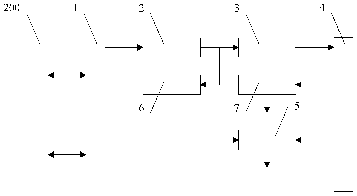
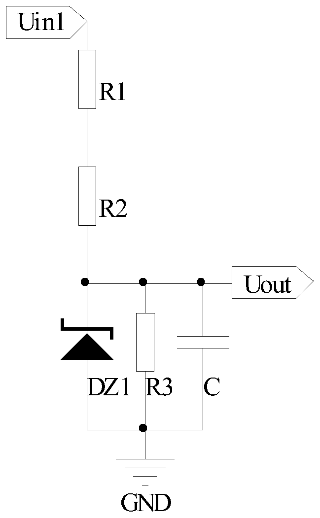
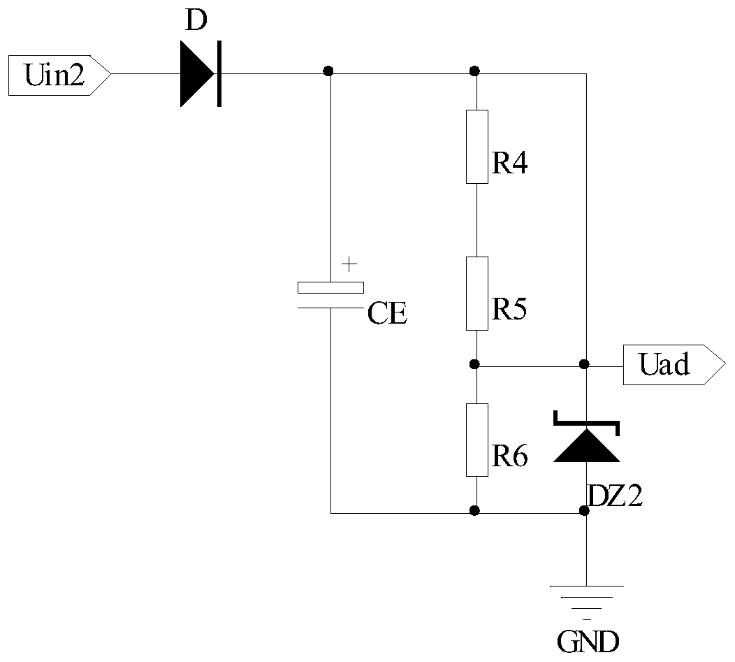
[0042] Please refer to Figure 1 to Figure 4 , Embodiment 1 of the present invention is:

[0043] A dimmer, which can be controlled by bluetooth, and is used to be connected in series with a load lamp, including a zero-crossing detection circuit 6, a voltage detection circuit 7, a MOS tube switch circuit 1 connected in series, a full-wave rectification circuit 2, a filter circuit 3, a step-down circuit 4 and a single-chip microcomputer, the MOS tube switch circuit 1 is used to be electrically connected to the single live wire power supply terminal 200, the zero-crossing detection circuit 6 is electrically connected to the output terminal of the full-wave rectification circuit 2 and the single-chip microcomputer, and the voltage detection circuit 7 are respectively electrically connected to the output end of the filter circuit 3 and the single-chip electromechanical; the single-chip electromechanical connection has a matching peripheral circuit, and the single-chip microcompute...


PUM


Abstract

The invention provides a light regulator which is used for being connected in series with a load lamp. The light regulator comprises an MOS transistor switching circuit, a full wave rectifying circuit, a filter circuit, a step-down circuit and a microcontroller which are connected in series. The MOS transistor switching circuit is used for being electrically connected with a single-live-wire powersupply end. The light regulator also comprises a zero cross detection circuit and a voltage detection circuit. The zero cross detection circuit is electrically connected with the output end of the full wave rectifying circuit and the microcontroller. The voltage detection circuit is electrically connected with the output end of the filter circuit and the microcontroller. The microcontroller is used for regulating the PWM value according to the voltage detection value outputted by the voltage detection circuit until the input voltage of the light regulator is matched with the voltage of the load lamp. The load compatibility of the light regulator can be enhanced, the maximum brightness of the load lamp can be enhanced to the greatest extent without flickering of the load lamp or influencing the light-up response speed and thus the user experience can be enhanced.

Description

technical field [0001] The invention relates to the technical field of dimming, in particular to a dimmer. Background technique [0002] Single live wire power supply refers to only using the switch in series with the lamp to control the live wire (phase wire), and to realize the direct power supply to the electronic switch, smart switch and super switch installed on the wall without directly connecting the neutral wire. With the development of single live wire power supply technology, there are more and more varieties of single live wire power supply dimmers on the market. However, most dimmers powered by single live wire cannot be compatible with all load lights at the same time. This is because the maximum phase cut angle of the output of the traditional single live wire rear-cut dimmer is fixed. Sometimes it is easy to cause insufficient power supply of the dimmer and flicker or power failure. Contents of the invention [0003] The technical problem to be solved by t...

Claims


Application Information

Patent Timeline
Patent Type & Authority Patents(China)
IPC IPC(8): H05B37/02
CPCH05B47/10
Inventor 李水旺王文健郭文斌
Owner XIAMEN YADE ELECTRONICS TECH
Learn More