Conductive foam for fingerprint identification

A conductive foam and fingerprint recognition technology, which is applied in the direction of electrical components, magnetic/electric field shielding, coating, etc., can solve the problems of high resistance and large compression force of conductive foam, and achieve small resistance, low compression force, and good conductivity. The effect of grounding performance

Pending Publication Date: 2018-05-15
昆山汉品电子有限公司
View PDF5 Cites 2 Cited by
  • Summary
  • Abstract
  • Description
  • Claims
  • Application Information

AI Technical Summary

Problems solved by technology

[0003] At present, the conductive foam of the existing products has the problem of excessive compression force while ensuring the electrical conductivity. However, in the prior art, electroplating metal on the sponge is usually used to make conductive foam with a small compression force. Reduce the weight of the conductive cloth, but the conductive foam of this structure has the problem of high resistance. Usually, the compression rate is greater than 15N when compressed to the required thickness, and the compression force is required to be less than 5N in fingerprint recognition applications. Therefore, ordinary conductive foam Foam cannot meet the corresponding requirements, so the above-mentioned problems are urgent problems to be solved in this field

Method used


Image

  • Conductive foam for fingerprint identification
  • Conductive foam for fingerprint identification

Examples


Embodiment Construction

[0015] The present invention will be further described below in conjunction with the accompanying drawings and specific embodiments.

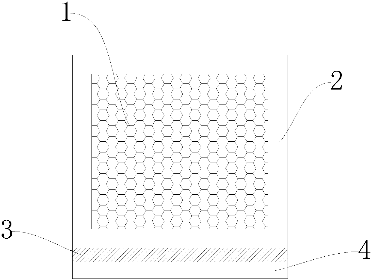
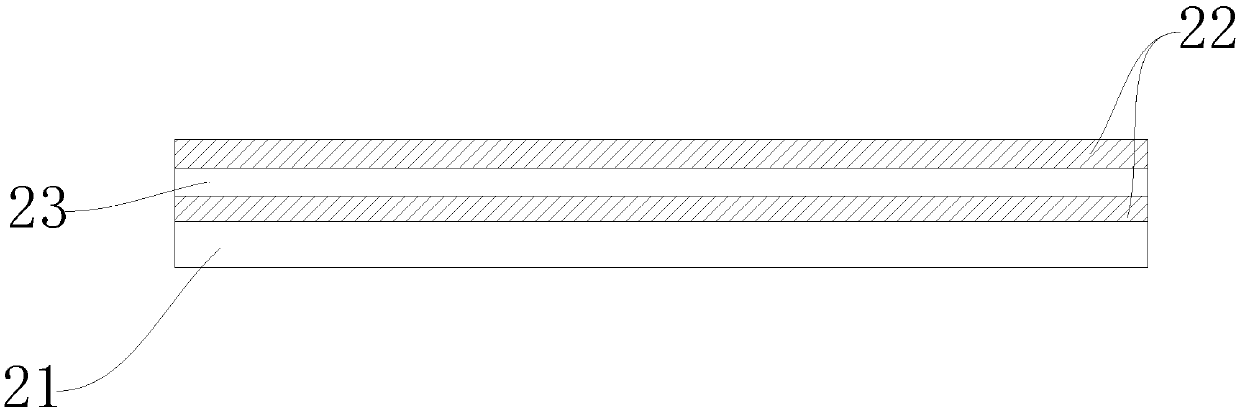
[0016] Such as figure 1 and figure 2 As shown, the conductive foam for fingerprint identification includes foam 1 as the inner core, and the foam 1 is provided with an outer cladding, and the outer cladding is conductive fiber 2 that can completely wrap the foam 1 therein, the Conductive fiber 2 comprises polyester fiber 21 base material, and nickel 22, copper 23, nickel 22 are electroplated successively on described polyester fiber 21 base material so as to form conductive layer, because polyester fiber is provided with conductive layer, thereby can play The function of electromagnetic shielding, in addition, the conductive fiber 2 of this structure has an extremely low grammage and extremely low resistance, and its grammage is 30g / m 2 up to 50g / m 2 , the resistance is less than 0.05ohms / inch 2 The other side of the polyester fiber 21 bas...


PUM

PropertyMeasurementUnit
thicknessaaaaaaaaaa
Basis weightaaaaaaaaaa
tackinessaaaaaaaaaa

Abstract

The invention discloses conductive foam for fingerprint identification. The conductive foam comprises foam serving as a core, wherein conductive fibers are arranged outside the foam to serve as a coating layer; the foam density is 10-50kg/m<2>; the conductive fibers comprise a polyester fiber base material, conductive layers formed by nickel, copper and nickel are sequentially arranged on one sideof the polyester fiber base material, and the other side of the polyester fiber base material is connected with the foam; and conductive two-sided adhesive is arranged on one side or two opposite sides of the outer side of the conductive fibers when the conductive fibers coat the foam. According to the conductive foam, the foam having the density of 10-50kg/m<2> is selected as a core, the compressing force can be effectively reduced; and in the structure of the conductive fibers, the conductive layers formed by nickel, copper and nickel are arranged on the polyester fibers, so that the conductive fibers with the structure have an extremely low gram weight which is 30-50g/m<2> and extremely low resistance which is less than 0.05ohms/inch<2>, so that the conductive foam has extremely low compressing force, relatively small resistance and extremely high pressing sensitivity, and is suitable for fingerprint identification.

Description

technical field [0001] The invention relates to a conductive foam, in particular to a conductive foam for fingerprint identification. Background technique [0002] Conductive foam is to wrap conductive cloth on flame-retardant sponge. After a series of treatments, it has good surface conductivity and can be easily fixed on the device to be shielded with adhesive tape. [0003] At present, the conductive foam of the existing products has the problem of excessive compression force while ensuring the electrical conductivity. However, in the prior art, electroplating metal on the sponge is usually used to make conductive foam with a small compression force. Reduce the weight of the conductive cloth, but the conductive foam of this structure has the problem of high resistance. Usually, the compression rate is greater than 15N when compressed to the required thickness, and the compression force is required to be less than 5N in fingerprint recognition applications. Therefore, ordi...

Claims


Application Information

Patent Timeline
Patent Type & Authority Applications(China)
IPC IPC(8): H05K9/00B32B27/08B32B27/12B32B27/40B32B27/36B32B27/02B32B7/12B32B7/06B32B33/00
CPCH05K9/0088H05K9/009B32B5/02B32B7/06B32B7/12B32B27/065B32B27/08B32B27/12B32B27/40B32B33/00B32B2255/02B32B2255/205B32B2262/0276B32B2307/7265B32B2307/7246B32B2266/0278B32B2307/202
Inventor 邓联文吴娜娜
Owner 昆山汉品电子有限公司
Why Eureka
Try Eureka