Wearable electrical stimulator

An electrical stimulation and electrode pad technology, applied in implanted stimulators, electrotherapy, artificial respiration, etc., can solve the problems of constant treatment parameters, single treatment mode, limitations, etc., to achieve both sedative functions and improved nerve excitability. , the effect of meeting the needs of individualized treatment

Pending Publication Date: 2018-05-18
深圳华瑞技术有限公司
View PDF6 Cites 3 Cited by
  • Summary
  • Abstract
  • Description
  • Claims
  • Application Information

AI Technical Summary

Problems solved by technology

[0003] However, the existing electrical stimulation physiotherapy apparatus has problems such as constant treatment parameters, single treatment mode, or the need for professional operators to operate or guide, making it impossible for people t

Method used


Image

  • Wearable electrical stimulator
  • Wearable electrical stimulator
  • Wearable electrical stimulator

Examples


Embodiment 1

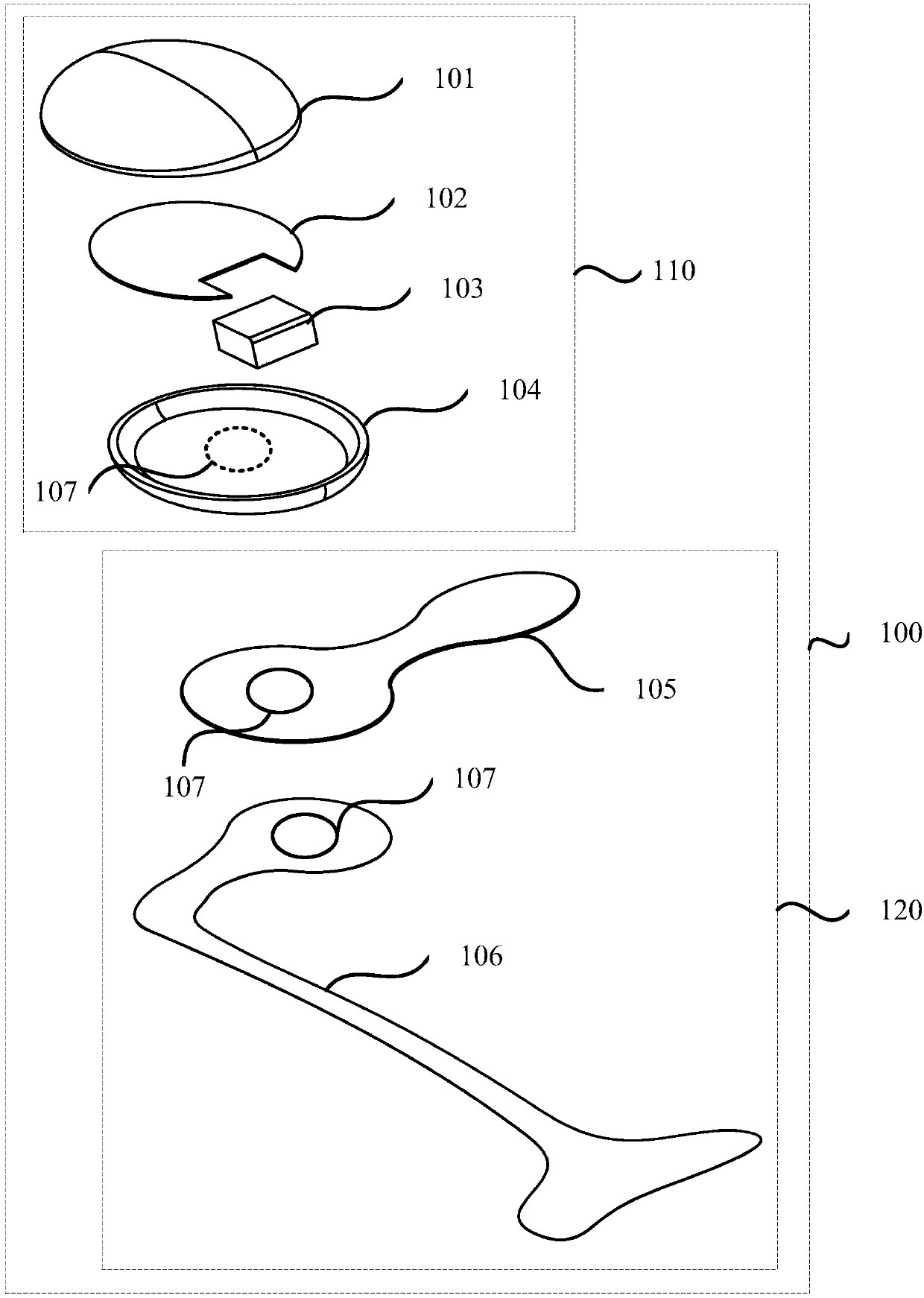
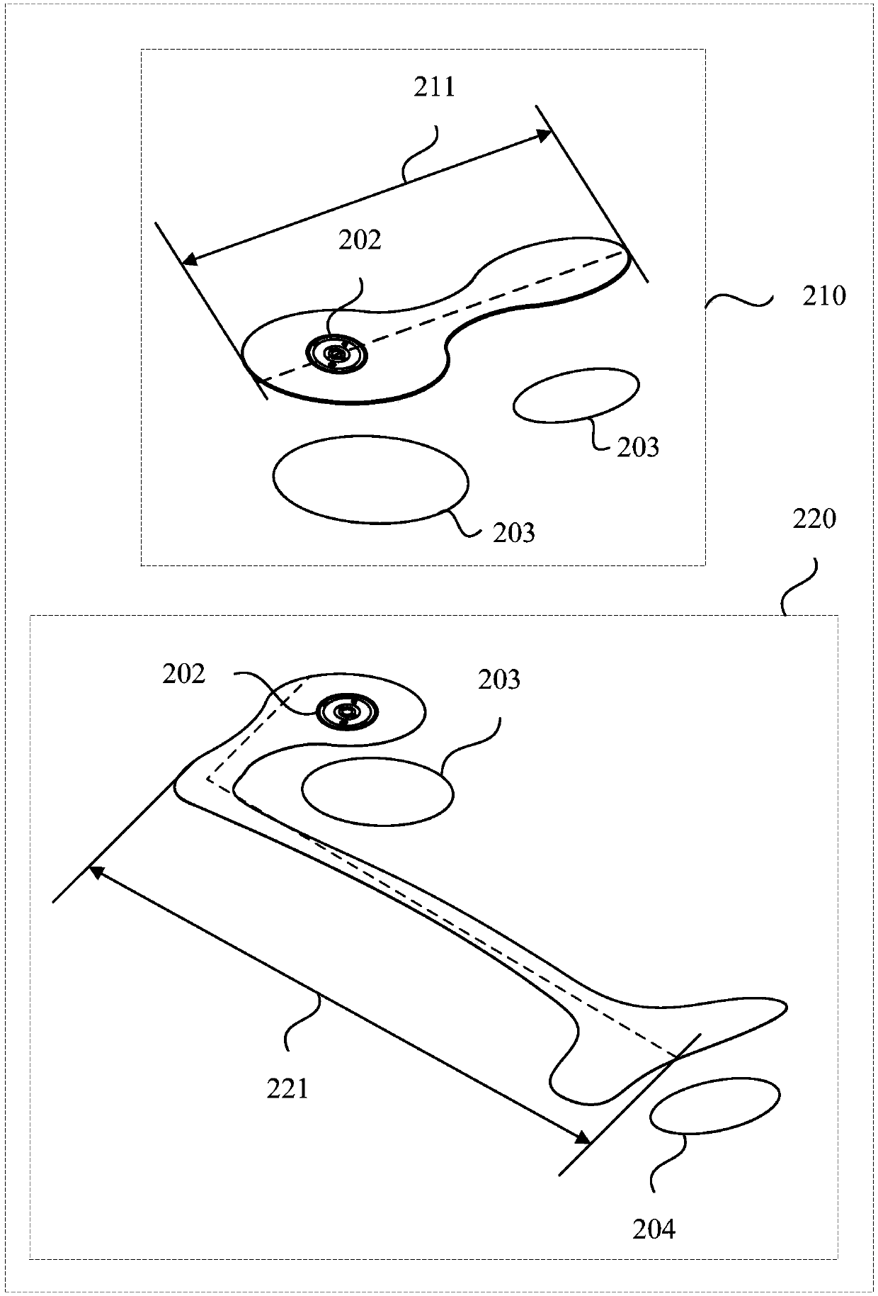
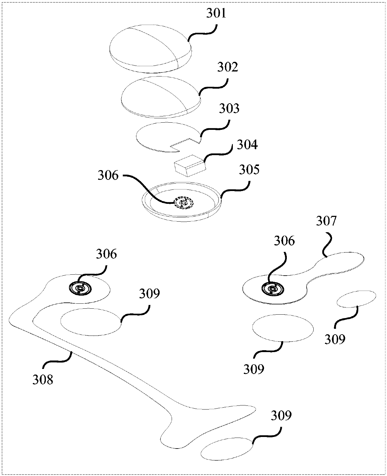
[0053] see figure 1 , the present embodiment provides a wearable electrical stimulator 100, comprising: an upper shell 101, a lower shell 104, a power supply device 103, a control device 102, a stabilizing electrode piece 105 and an exciting electrode piece 106; the upper shell 101 and the lower shell 104 connected to package the electrically connected power supply unit 103 and the control unit 102; the control unit 102 is used to generate a stabilizing pulse signal or an exciting pulse signal according to the mode selection signal and the output current gear signal; the stabilizing electrode piece 105 and the lower shell 104 pass through The conductive connecting device 107 is used to connect the calming pulse signal to the human body through the cervical nerve; the exciting electrode piece 106 is connected to the lower shell 104 through the conductive connecting device 107, and is used to pass the excited pulse signal through the facial nerve temporal branch and the right tr...

Embodiment 2

[0070] This embodiment is based on the first embodiment above, and further describes the "control device" and "power supply device" in the above embodiment, and the explanation of the same or corresponding devices and terms as the above embodiment, in this embodiment No longer.

[0071] see Figure 4 , on the basis of the above embodiments, the control device 410 of the wearable electrical stimulator in this embodiment includes:

[0072] The switch module 411 is used to control the start-up or shutdown of the wearable electric stimulator according to the received start-up signal or shutdown signal;

[0073] The wireless communication module 412 is used to receive the working status signal or the mode selection signal and the output current gear signal sent by the mobile terminal 400, and transmit the working status signal or the mode selection signal and the output current gear signal to control module 413;

[0074] A control module 413, configured to determine a set freque...


PUM


Abstract

The embodiment of the invention discloses a wearable electrical stimulator. The wearable electrical stimulator comprises an upper cover, a lower cover, a power supply device, a control device, a calming electrode tab and an exciting electrode tab; the upper cover is connected with the lower cover to encapsulate the power supply device and the control device which are electrically connected; the control device is used for selecting signals and outputting current shift signals according to the mode, and generating calming impulse signals or exciting impulse signals; the calming electrode tab isused for applying the calming impulse signals to a human body through the cervical nerve; and the exciting electrode tab is used for applying the exciting impulse signals to the human body through thetemporal branch of the facial nerve and the right trigeminal nerve. According to the wearable electrical stimulator, for the first time, two different working modes of calm nerves and excitatory nerves are integrated into a wearable device, so that a user can configure the corresponding electrode tab, treatment mode and treatment intensity according to his/her own condition, so that the needs ofpersonalized treatment for the user is met, both calming function and enhancing nerve excitability function are achieved.

Description

technical field [0001] Embodiments of the present invention relate to electrotherapy device technology, in particular to a wearable electric stimulator. Background technique [0002] Due to the technical characteristics of non-invasive, non-invasive, good tolerance, short-term effect and no side effects of transcutaneous electrical nerve signal method, it has become a hot spot in clinical application research. Electrical stimulation physiotherapy device can be used to improve reading, cognition and sleep disorders, etc. [0003] However, the existing electrical stimulation physiotherapy apparatus has problems such as constant treatment parameters, single treatment mode, or the need for professional operators to operate or guide, making it impossible for people to perform corresponding treatment according to individual needs in daily life, delaying treatment. The timeliness also limits the application of electrical stimulators based on transcutaneous electrical nerve signal ...

Claims


Application Information

Patent Timeline
IPC IPC(8): A61N1/36
CPCA61N1/3605A61N1/36078A61N1/36128A61N1/36153A61N1/36171
Inventor 罗飞李军宋鹤然秋云海
Owner 深圳华瑞技术有限公司
Why Eureka
Try Eureka