
Pneumatic apparatus on vehicle socket sleeve fabric napping machine

A kind of pneumatic device, the technology of hair pulling machine, which is applied in the direction of fabric surface trimming, textile and paper making, roughening, etc., can solve the problems of poor hair pulling effect, poor fabric durability and shape retention, and inability to pile and shape, so as to improve the protection. The effect of shape and durability, increase in rolling line speed, and increase in pull strength

Active Publication Date: 2018-05-18
求法问律(菏泽)法律咨询服务有限公司
View PDF3 Cites 2 Cited by
  • Summary
  • Abstract
  • Description
  • Claims
  • Application Information

AI Technical Summary

Problems solved by technology

[0003] 1. During the napping process, the plush density is relatively high, and the formed terry cloth has strips of plush and cannot be evenly distributed;
[0004] 2. The plush falls into the napping cylinder and the main cylinder, forming accumulations, resulting in the failure of the napping cylinder to rotate, so that the napping effect becomes poor;
[0005] 3. The napping cylinder rotates under the drive of the cloth, which has instability and inhomogeneity, which affects the napping effect and the uniformity of napping;
[0006] 4. The napping needle is linear. Although it can comb the plush, the napping efficiency is extremely low, and the napping process takes a long time;
[0007] 5. The plush cannot be shaped during the napping process, resulting in poor durability and shape retention of the fabric

Method used


Image

  • Pneumatic apparatus on vehicle socket sleeve fabric napping machine
  • Pneumatic apparatus on vehicle socket sleeve fabric napping machine
  • Pneumatic apparatus on vehicle socket sleeve fabric napping machine

Examples


Embodiment Construction

[0036] The following are specific embodiments of the present invention and in conjunction with the accompanying drawings, the technical solutions of the present invention are further described, but the present invention is not limited to these embodiments.

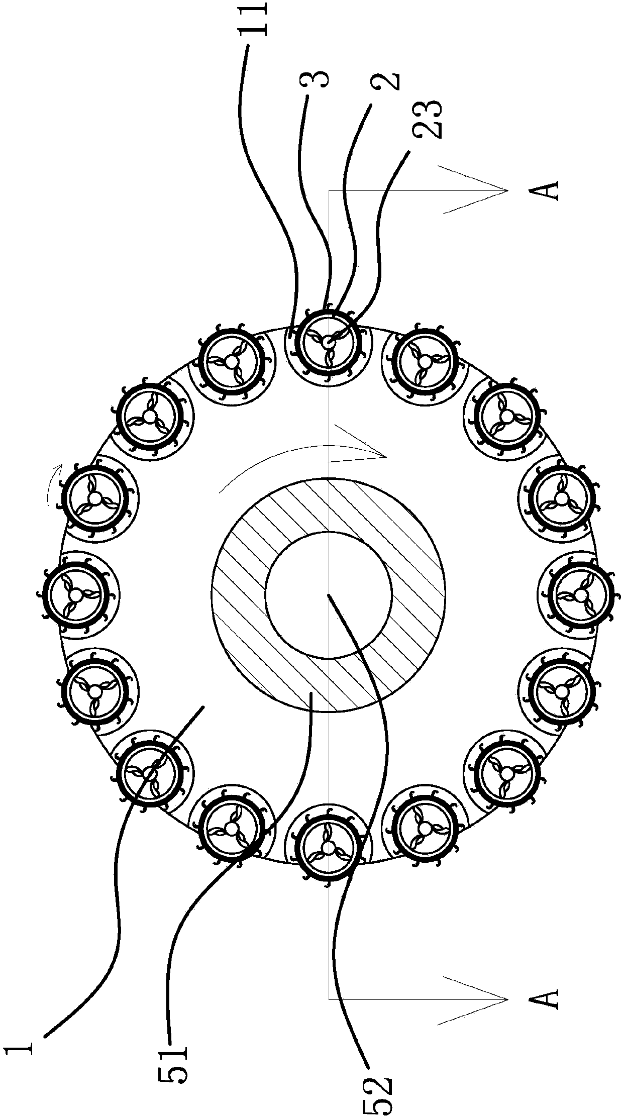
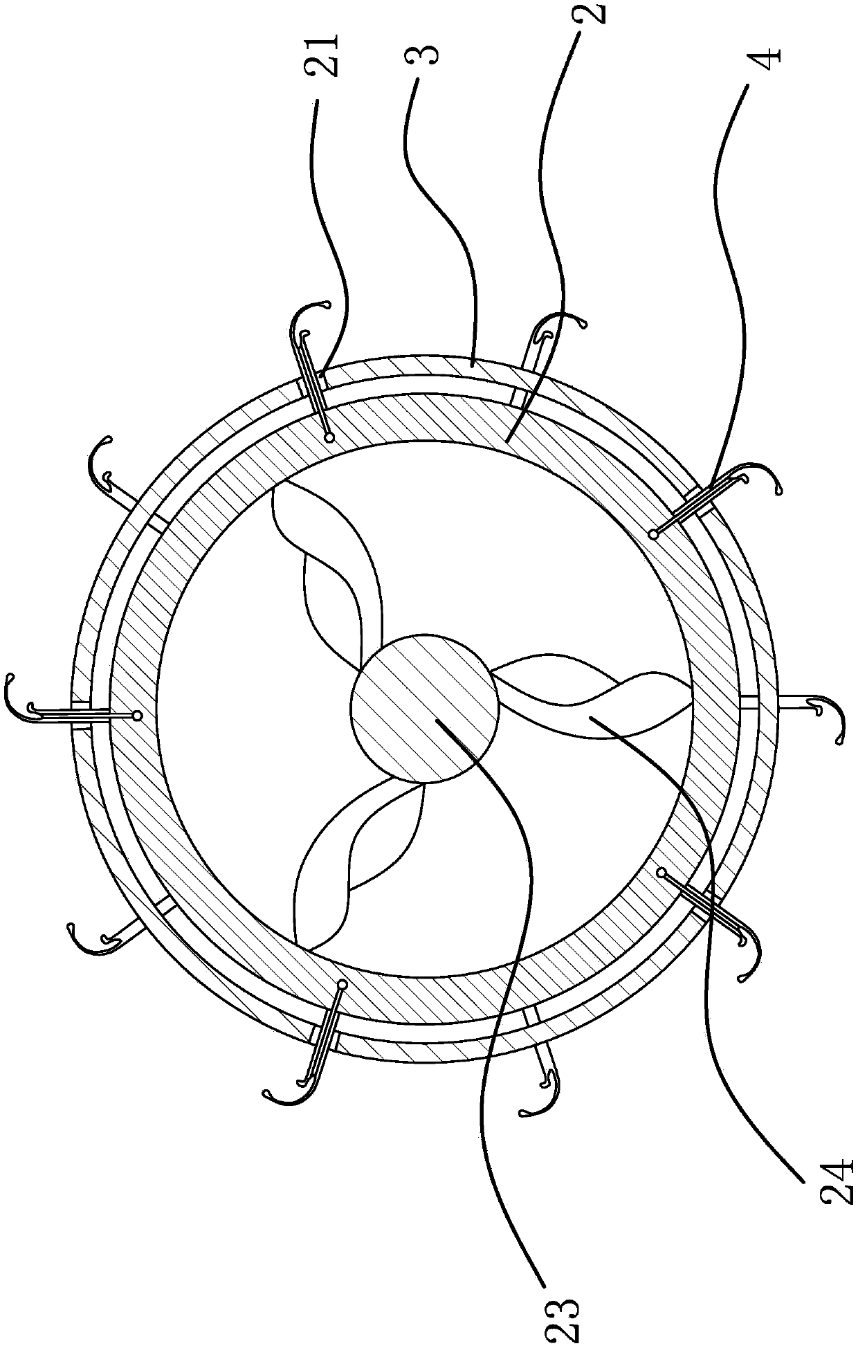
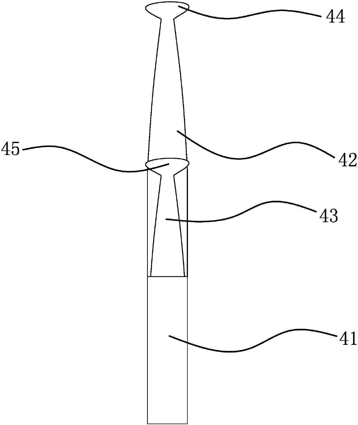
[0037] Such as figure 1 , figure 2 , Figure 5 , Figure 6 and Figure 7 As shown, the napping machine includes a main cylinder 1, several napping cylinders 2, a guide sleeve 3 corresponding to the napping cylinders 2 and a blower. The cylinder 2 is arranged in the corresponding avoidance opening 11, and the napping cylinder 2 partially protrudes from the avoidance opening 11, and a plurality of pull needles 4 are evenly arranged on the napping cylinder 2, and several guide sleeves 3 are provided with a plurality of holes arranged on the circumference of the guide sleeve 3. Guide groove 21, the guide groove 21 is corrugated, the guide sleeve 3 is fixedly connected with the main cylinder 1, the pull needle 4 is inserte...


PUM


Abstract

The invention provides a pneumatic apparatus on a vehicle socket sleeve fabric napping machine, and belongs to the technical field of textile. In the prior art, the existing napping machine has the low efficiency so as to easily cause damage on cloths and the like. A purpose of the present invention is to solve the technical problems in the prior art. According to the pneumatic apparatus, a plurality of napping needles are uniformly arranged on napping drums, guide sleeves are provided with a plurality of guide grooves arranged on the circumferential surfaces of the guide sleeves, the guide grooves are corrugated, the guide sleeves are fixedly connected to a main drum, the napping needles are arranged in the guide grooves, ventilation cavities are arranged in the napping drums, a rotationshaft is arranged in the ventilation cavity, and is provided with a blade wheel, the blade wheel is connected to the interior of the napping drum, the rotation shaft is rotatably to the main drum, a transmission shaft is provided with a gas flow inlet, the main drum is provided with wind inlet holes corresponding to avoidance ports one by one, and the wind inlet holes are communicated to the gas flow inlet, and are communicated to the corresponding ventilation cavities. The pneumatic apparatus of the present invention has advantages of high napping efficiency, fabric protection and the like.

Description

technical field [0001] The invention belongs to the technical field of textiles, and relates to a pneumatic device on a napping machine for automobile seat cover fabrics. Background technique [0002] The terry cloth used for the car seat cover is due to its own fiber structure. The prior art utilizes the sun wheel (main roller) and the planetary wheel (i.e. the napping roller) to realize napping, wherein the napping roller is passively rotated under the drive of the cloth. Analysis shows that the prior art has the following defects: [0003] 1. During the napping process, the plush density is relatively high, and the formed terry cloth has strips of plush and cannot be evenly distributed; [0004] 2. The plush falls into the napping cylinder and the main cylinder, forming accumulations, resulting in the failure of the napping cylinder to rotate, so that the napping effect becomes poor; [0005] 3. The napping cylinder rotates under the drive of the cloth, which has instab...

Claims


Application Information

Patent Timeline
IPC IPC(8): D06C11/00
CPCD06C11/00
Inventor 王键
Owner 求法问律(菏泽)法律咨询服务有限公司
Learn More