[0032] In order to make the objectives, technical solutions, and advantages of the present invention clearer, the present invention will be further described in detail below with reference to the accompanying drawings and preferred embodiments. However, it should be noted that many details listed in the specification are only to enable the reader to have a thorough understanding of one or more aspects of the present invention, and these aspects of the present invention can be implemented even without these specific details.
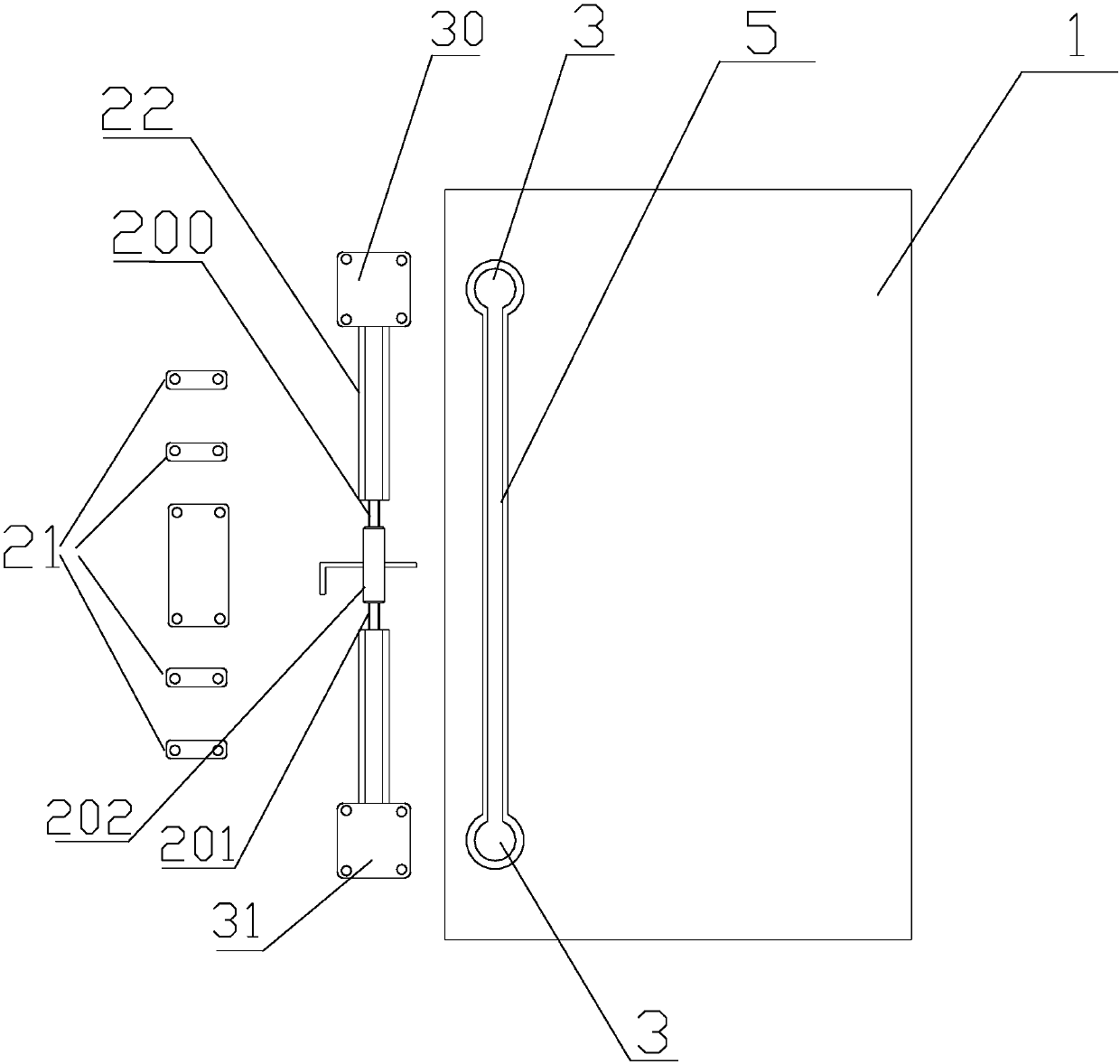
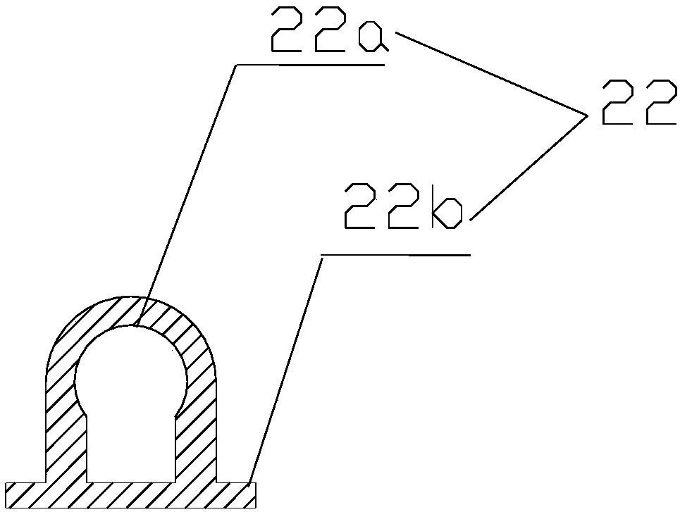
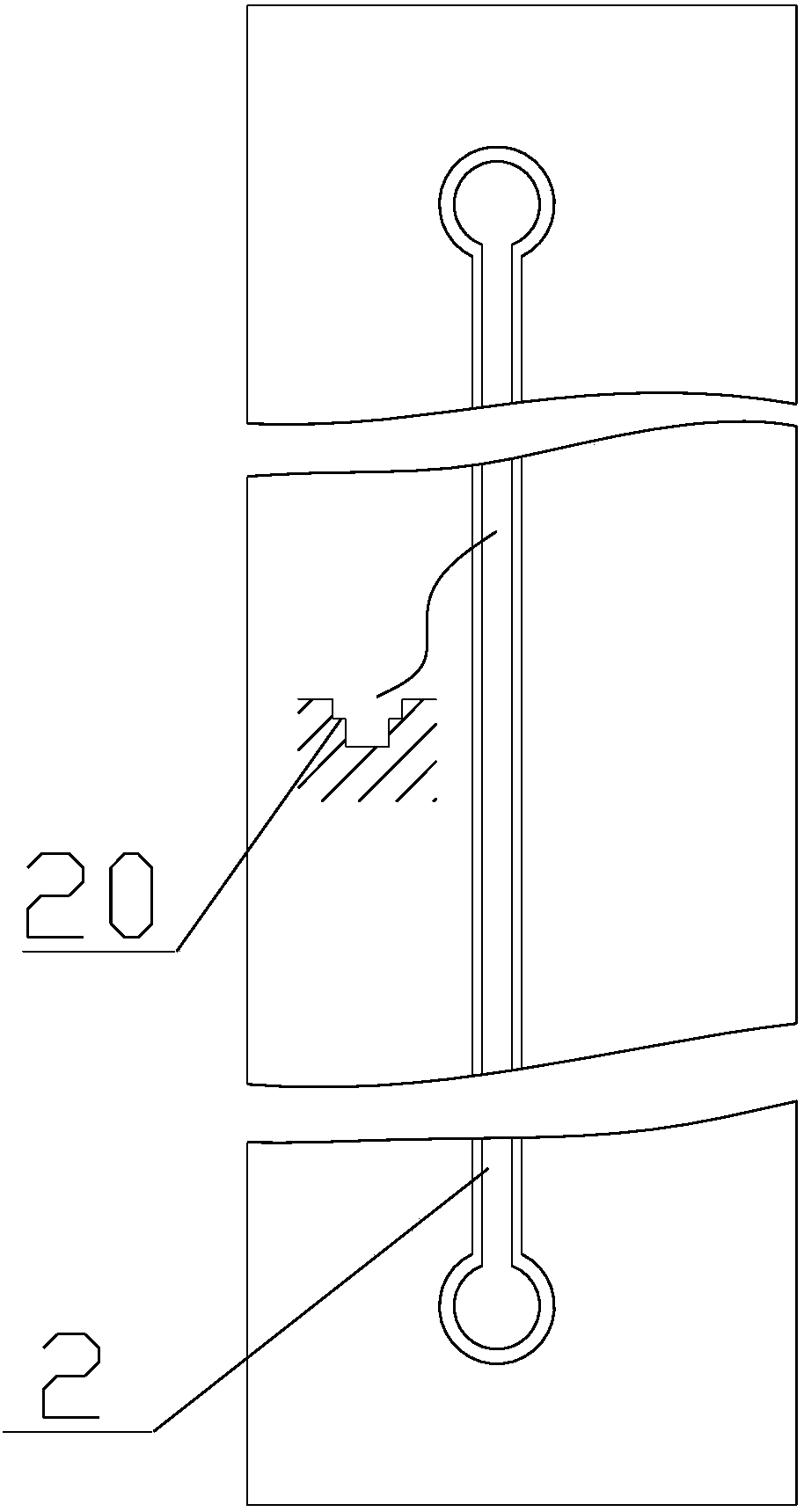
[0033] Such as figure 1 , figure 2 with image 3 As shown, according to the present invention, an anti-deformation device for the door panel of a wooden jewelry cabinet includes a door panel 1 and one or more longitudinally vertical reserved grooves 2 opened on the back surface of the door panel 1, and the reserved grooves 2 are inlaid with An adjustable telescopic rod structure 5 for preventing deformation of the door panel 1. The reserved groove 2 is close to the upper end edge of the back surface of the door panel 1 and extends vertically to the lower end edge. The upper and lower ends of the reserved groove 2 are provided The upper counterbore 3 and the lower counterbore 4 are formed integrally with the reserved groove, and the adjustable telescopic rod structure 5 is matched and embedded in the reserved groove 2 and the upper counterbore 3 so as to be fixed and integrated. The reserved groove The width of 2 is 10mm-18mm, and the depth is 10mm-15mm. In the present invention, a step 20 and a strip-shaped fixing member 21 are provided on the edge of the slot of the reserved groove 2. The strip-shaped fixing member 21 is perpendicular to the convex tube 22 and is fixed on the door panel 1 by bolts. , The upper counterbore 3 is matched and embedded with an upper support seat 30, and the lower support seat 31 is matched and embedded in the lower counterbore 4, and the upper end of the adjustable telescopic rod structure 5 and the upper support seat 30 Connected, the lower end of the adjustable telescopic rod structure 5 is connected to the lower support base 31, the adjustable telescopic rod structure 5 is sleeved with a convex tube 22, and the convex tube 22 is connected to the embedded The step 20 is matched and fixed, so that the adjustable telescopic rod structure 5 is connected with the upper support base 30 and the lower support base 31 to form an integrated body and then is embedded in the reserved groove 2, the upper counterbore 3 and the lower counterbore 4 , And the protruding portion 22a and side wings 22b of the convex tube 22 are sequentially embedded in the groove of the reserved groove 2 and on the step 20;
[0034] In the present invention, such as figure 1 , figure 2 , image 3 , Figure 4 , Figure 5 with Image 6 As shown, the telescopic rod structure 5 includes an orthodontic screw 200, a reverse screw 201, and a positive and negative connecting tube 202 sheathed in the convex tube 22. The upper end of the orthodontic screw 200 Connected to the upper support base 30, the lower end of the anti-thread screw 201 is connected to the lower support base 31, and the lower end of the orthodontic screw 200 is connected to the anti-thread screw through a positive and negative connection tube 202. The upper end of the 201 is threaded, and the orthodontic screw 200, the reverse screw 201, and the positive and negative connection tube 202 are sleeved in the convex tube 22, and then the strip fixing member 21 is bolted to the door panel 1 to fix it, so that the orthodontic screw 200 and the anti-dental screw 201 are connected to the upper support base 30 and the lower support base 31 to form an integrated body and then are embedded in the reserved groove 2, the upper counterbore 3 and In the sink hole 4, a plurality of recessed holes 204 are opened on the surface of the front and back connecting pipe 202, and the recessed holes 204 are distributed in a spiral shape on the surface of the front and back connecting pipe 202, such as Figure 7 As shown, use a pointed screwdriver or hexagonal wrench 6 to insert into the recessed hole 204 to rotate the front and back teeth connecting tube 202, so that the orthodontic screw 200 and the reverse screw 201 are contracted or extended toward the inside and outside of the door panel until the door panel is restored to a straight line. , And then seal the slot of reserved slot 2. In the present invention, such as Figure 8 As shown, a plurality of protruding rods 205 are provided on the surface of the front and back teeth connecting pipe 202, and the protruding rods 205 are distributed in a spiral shape on the surface of the front and back teeth connecting pipe 202. After the protruding rod of the column 205 is a hexagonal protruding rod instead of the concave hole 204, an Allen wrench can be used to cover the protruding post 205 to rotate the positive and negative connection pipe 202 until the door panel is restored to a straight line.
[0035] In the present invention, in the present invention, such as figure 1 , figure 2 , image 3 , Figure 4 , Figure 5 So and Image 6 As shown, the upper support base 30 includes an upper support portion 30a, an upper support column 30b, and an upper screw connection portion 30c, and the lower support base 31 includes a lower support portion 31a, a lower support column 31b, and a lower screw connection portion 31c; The upper support column 30b is arranged in the center of the bottom surface of the upper support portion 30a and is matched and embedded in the upper counterbore 3, and the upper screw connecting portion 30c is arranged on the side of the upper support portion 30a and is connected to the upper support portion 30a. The reserved groove 2 is on the same axis, and the upper screw connecting portion 30c is connected to the upper end of the orthodontic screw 200; the lower support column 31b is arranged in the center of the bottom surface of the lower support portion 31a and is matched and embedded In the sink hole 4, the lower screw connecting portion 31c is arranged on the side of the lower supporting portion 31a and on the same axis as the reserved groove 2, and the lower supporting column 31b is arranged on the At the center of the bottom surface of the lower support portion 31a, the lower screw connecting portion 31c is connected to the lower end of the anti-thread screw 201, and the upper support column 30b and the lower support column 31b are respectively inserted into the upper counterbore 3 and the counterbore 4 Fix it so that the orthodontic screw 200 and the anti-screw 201 can be easily installed in the reserved groove 2. When the orthodontic screw 200 and the anti-screw 201 are adjusted to expand and contract to push the upper support column 30b and the lower support Column 31b enables the upper support column 30b and the lower support column 31b to push the inner walls of the upper counterbore 3 and the lower counterbore 4, respectively, until the door panel is restored to be straight, thereby effectively repairing the door panel from changing its size due to expansion and effectively preventing the door panel from expanding. For problems such as deformation and warpage, the upper counterbore 3 and the lower counterbore 4 are round, square or triangular.
[0036] As another embodiment of the present invention, the number of reserved grooves 2 opened on the back surface of the door panel 1 is two and is close to the long side edge of the back of the door panel, and the distance between the reserved groove 2 and the long side edge of the door panel 1 is 40 -65mm. In addition, the two reserved slots 2 are located on the two long edges of the door panel and are parallel to the edges. The adjustable telescopic rod structure 4 is placed in the two reserved slots 2 to adjust the adjustable telescopic rod structure on the side of the free end of the door panel. 4. For uneven door panels, use the adjustable telescopic rod structure 4 close to the hinge 7 side (the side hinged to the cabinet body) to make further fine adjustments to make the door panel flatter. Refer to the attachment for the specific adjustment process. figure 1 The adjustment method.
[0037] According to another aspect of the present invention, the present invention provides a method for assembling an anti-deformation device for a door panel of a wooden ornament cabinet: including the following steps:
[0038] Step 1: Provide a door panel 1 with a predetermined thickness and a moisture content not higher than 28%. The length of the door panel 1 is 28 to 36 times the thickness of the wooden board;
[0039] Step 2: Open one or more longitudinally vertical reserved grooves 2 on the back surface of the door panel 1 so that the reserved grooves 2 are close to the upper edge of the back surface of the door panel 1 and extend vertically to The lower end edge, and the upper and lower ends of the reserved groove 2 are provided with an upper counterbore 3 and a lower counterbore 4 integral with the reserved groove 2, and a step 20 is formed on the edge of the reserved groove 2 , And then use a hot blower to preheat and dry the reserved groove 2 and the upper counterbore 3 and the lower counterbore 4 for 10-20 minutes;
[0040] Step 3: Inlay the adjustable telescopic rod structure to prevent the deformation of the door panel in the reserved groove 2 and the counterbore and sink hole; firstly, a protruding tube 22 is sleeved outside the adjustable telescopic rod structure 5, and a strip The shaped fixing member 21 is perpendicular to the convex tube 22 and is fixed on the door panel by bolts; secondly, an upper supporting seat 30 is matched and embedded in the upper counterbore 3, and a lower supporting seat 30 is matched and embedded in the sink hole 4 The support base 31, the upper end of the adjustable telescopic rod structure 5 is connected to the upper support base, and the lower end of the adjustable telescopic rod structure 5 is connected to the lower support base 31; finally, the convex tube 22 is connected to the upper support base. The embedded step 20 is matched and fixed, so that the adjustable telescopic rod structure 5 is connected with the upper support base 30 and the lower support base 31 to form an integrated body and then is embedded in the reserved groove 2, the upper counterbore 3 and the counterbore 4 ;
[0041] Step 4: Adjust the supporting force between the adjustable telescopic rod structure 5 and the reserved groove 2, the upper counterbore 3 and the lower counterbore 4, so that the door panel is kept flat, and the adjusted and installed door panel 1 is dried or After the drying moisture content is lower than 10%, adjust the supporting force between the adjustable telescopic rod structure 5 and the door panel 1 again. Through the adjustment of internal force, by adjusting the moisture content of the door panel, the internal force adjustment measures are maintained to keep the door panel flat and smooth. It has good prestress, so that the door panel is not easy to deform.
[0042] The above are only the preferred embodiments of the present invention. It should be pointed out that for those of ordinary skill in the art, without departing from the principle of the present invention, several improvements and modifications can be made, and these improvements and modifications should also be made. It is regarded as the protection scope of the present invention.