A high-load truss-type high-flexibility mechanism

A truss-type, highly flexible technology, which is applied in the direction of manipulators, mechanical equipment, program-controlled manipulators, etc., can solve the problems that flexible mechanisms are not suitable for complex and flexible deformation, and the deformation range is limited, so as to achieve unlimited actuation range and large deformation range , the effect of weight reduction

Active Publication Date: 2021-01-29
HARBIN INST OF TECH
View PDF7 Cites 0 Cited by
  • Summary
  • Abstract
  • Description
  • Claims
  • Application Information

AI Technical Summary

Problems solved by technology

[0004] In order to solve the problem that the existing flexible mechanism is not suitable for complex and flexible deformation and the deformation range is limited, the present invention further proposes a high-load-bearing truss-type high-flexibility mechanism

Method used


Image

  • A high-load truss-type high-flexibility mechanism
  • A high-load truss-type high-flexibility mechanism
  • A high-load truss-type high-flexibility mechanism

Examples


specific Embodiment approach 1

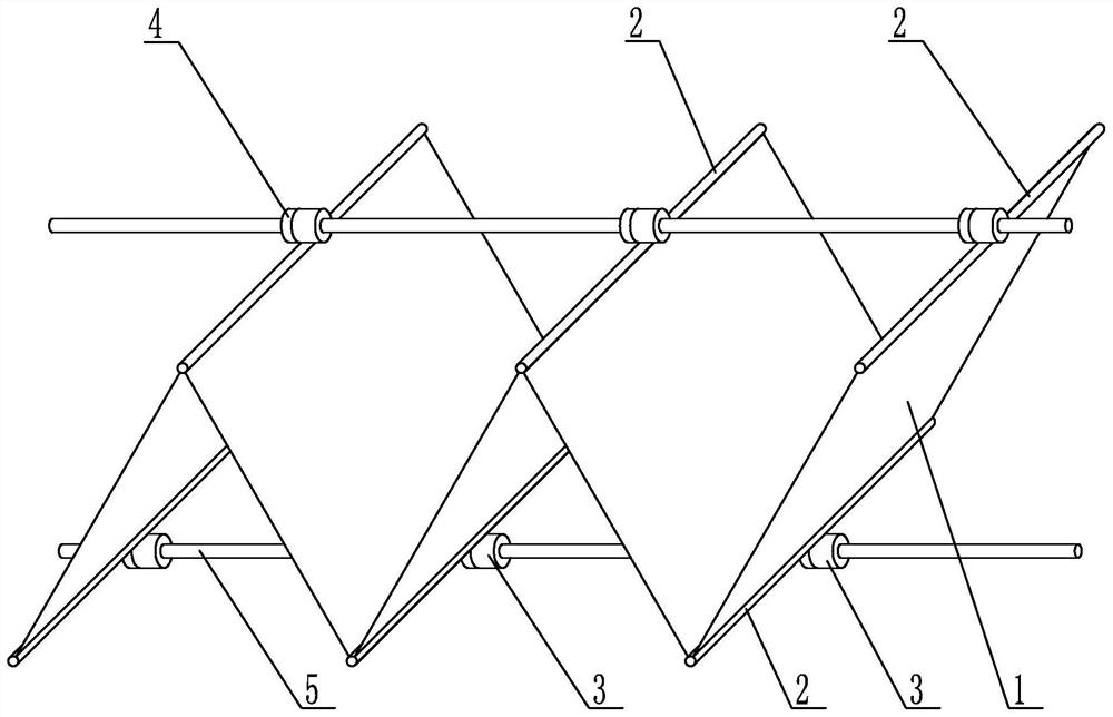
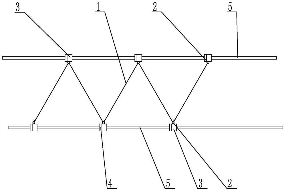
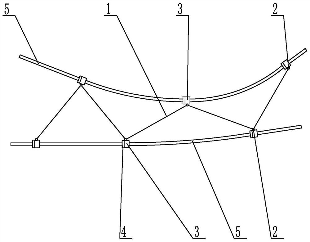
[0016] Specific implementation mode one: combine Figure 1 to Figure 5 Describe this embodiment, a high-load truss-type high-flexibility mechanism described in this embodiment includes multiple truss units 1, multiple hinges 2, multiple sliders 3, multiple actuators 4 and multiple flexible rods 5, A plurality of truss units 1 are sequentially connected as a whole through hinges 2. A slider 3 is fixedly connected to the hinge 2. The actuating mechanism 4 is fixedly connected to the slider 3. The slider 3 is set on the flexible rod 5. The slider 3 is in the Driven by the actuating mechanism 4, it moves along the flexible rod 5.

[0017] The truss unit 1 is connected end to end by the hinge 2 as a whole, the slider 3 is fixedly connected to the hinge 2, the actuating mechanism 4 is fixedly connected to the slider 3, the flexible rod 5 passes through the slider 3, and the slider 3 is connected to the actuator 4. Driven to move along the flexible rod 5.

[0018] The plurality of ...

specific Embodiment approach 2

[0023] Specific implementation mode two: combination Figure 1 to Figure 5 This embodiment will be described. The actuating mechanism 4 in this embodiment is an ultrasonic linear motor. Other compositions and connection methods are the same as those in Embodiment 1.

specific Embodiment approach 3

[0024] Specific implementation mode three: combination Figure 1 to Figure 5 To describe this embodiment, the hinge 2 in this embodiment is a flexible hinge made of continuous elastic material. Other compositions and connection modes are the same as those in Embodiment 1 or 2.


PUM


Abstract

A high-load-bearing truss type high-flexibility mechanism relates to a flexible mechanism. The invention aims to solve the problem that the existing flexible mechanism is not suitable for complex and flexible deformation and the deformation range is limited. The present invention comprises a plurality of truss units, a plurality of hinges, a plurality of sliders, a plurality of actuating mechanisms and a plurality of flexible rods. The plurality of truss units are sequentially connected as a whole through the hinges, and the sliders are fixedly connected to the hinges as a whole. The actuator is fixedly connected with the slide block, the slide block is sleeved on the flexible rod, and the slide block moves along the flexible rod driven by the actuator. The present invention is used for deformable equipment.

Description

technical field [0001] The invention relates to a flexible mechanism, in particular to a high-load-bearing truss type high-flexibility mechanism. Background technique [0002] Mechanical equipment often needs to achieve functions through controllable changes in shape. Traditional mechanisms such as articulated robotic arms, slide rails, and pistons often use rigid parts connected by kinematic pairs to achieve deformation and carry external forces. They have the characteristics of simple mechanisms and simple motion mechanisms. , but its deformation range is often limited by rigid components, and the position of each point of the mechanism during the deformation process often has a simple linear coupling and is not easy to form a complex and controllable shape. [0003] In recent years, with the development of equipment, the control of large deformations and complex shapes has sometimes become the key goal of mechanism design, such as flexible robots, large-scale space deploy...

Claims


Application Information

Patent Timeline
Patent Type & Authority Patents(China)
IPC IPC(8): F16H35/00B25J9/12
CPCB25J9/123F16H35/00
Inventor 武睿
Owner HARBIN INST OF TECH
Why Eureka
Try Eureka