Automatic separation equipment used for engine piston combined type oil ring bushing rings

An automatic separation and combination technology, applied in metal processing equipment, metal processing, manufacturing tools, etc., can solve the problem of inseparable, combined oil ring liner separation and automatic feeding process difficult to achieve, unable to achieve full automatic piston ring Assembly and other problems to achieve the effect of reducing labor intensity of workers and improving assembly efficiency

Active Publication Date: 2018-05-22
BINZHOU BOHAI PRECISION MACHINERY +1
View PDF4 Cites 5 Cited by
  • Summary
  • Abstract
  • Description
  • Claims
  • Application Information

AI Technical Summary

Problems solved by technology

The combined oil ring is composed of a lining ring and two scraper rings. The lining ring is a kind of elastic steel belt ring with a wavy structure. When the lining rings are stacked, the adjacent lining rings will fit very tightly. , it is impossible to separate them one by one through the general mechanical structure
[0003] With the continuous increase of domestic car production, the output of engine pistons using combined oil rings is also increasing, and the automatic assembly of piston rings has gradually become an industry trend. It is difficult to realize the separation and automatic feeding process of the type oil ring backing ring, so that the automatic assembly of the entire piston ring cannot be realized

Method used


Image

  • Automatic separation equipment used for engine piston combined type oil ring bushing rings
  • Automatic separation equipment used for engine piston combined type oil ring bushing rings
  • Automatic separation equipment used for engine piston combined type oil ring bushing rings

Examples


Embodiment Construction

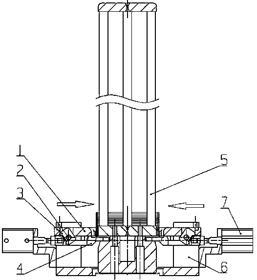
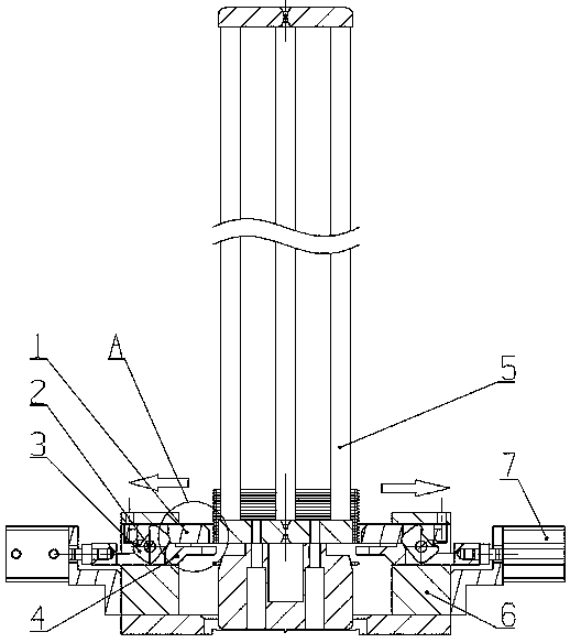
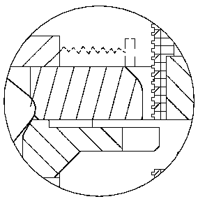
[0017] Accompanying drawing is a kind of specific embodiment of the present invention.

[0018] The automatic separation equipment for engine piston combined oil ring backing rings of the present invention includes a backing ring storage bin 5 and a cylinder propulsion mechanism, the backing ring storage bin 5 is a vertical frame structure of a rectangular frame or a cylindrical frame body, and the superimposed The lining ring is movable over the stand structure, and the lower end of the lining ring bin is connected with a cylinder propulsion mechanism, which is symmetrically installed on the left and right sides of the lining bin 5; the cylinder propulsion mechanism includes a cylinder 7, a dial block 3, and an upper slide plate 1. The lower plate 4 and the support 6, the displacement end of the cylinder 7 are movably connected to the shifting block 3, and the shifting block 3 is installed on the support 6 through the rotating pin 2; the displacement of the cylinder 7 drives t...


PUM


Abstract

The invention belongs to the technical field of gasoline engines and particularly relates to automatic separation equipment used for engine piston combined type oil ring bushing rings. The automatic separation equipment used for engine piston combined type oil ring bushing rings comprises a bushing ring stock bin and air cylinder propelling mechanisms. The lower end of the bushing ring stock bin is connected with the air cylinder propelling mechanisms. Each air cylinder propelling mechanism comprises an air cylinder, a shifting block, an upper sliding plate, a lower sliding plate and a support, wherein the shifting block is installed on the support through a rotating pin in a swing mode, the upper sliding plate and the lower sliding plate are placed in a support sliding rail, the lower sliding plate is connected with the displacement end of the air cylinder, the lower sliding plate reciprocates under the action of the air cylinder so as to touch the lower movable end point of the shifting block, the upper movable end point of the shifting block moves to touch the upper sliding plate in a swing mode, and a return spring connected to the support is installed on the upper sliding plate. The automatic separation equipment used for engine piston combined type oil ring bushing rings has the beneficial effects that one-by-one separation of combined oil ring bushing rings can be guaranteed, one bushing ring is separated and fed at each time, and thus full-automatic assembling of piston rings is realized, assembling efficiency is improved, and the labor intensity of workers is relieved.

Description

technical field [0001] The invention belongs to the technical field of gasoline engines, and in particular relates to an automatic separation device for an engine piston combined oil ring backing ring. Background technique [0002] At present, the oil rings of domestic engine pistons are mainly divided into two types: combined oil rings and integral oil rings, among which gasoline engine pistons mostly use combined oil rings. The combined oil ring is composed of a lining ring and two scraper rings. The lining ring is a kind of elastic steel belt ring with a wavy structure. When the lining rings are stacked, the adjacent lining rings will fit very tightly. , It is impossible to separate them one by one through the general mechanical structure. [0003] With the continuous increase of domestic car production, the output of engine pistons using combined oil rings is also increasing, and the automatic assembly of piston rings has gradually become an industry trend. It is diffi...

Claims


Application Information

Patent Timeline
Patent Type & Authority Applications(China)
IPC IPC(8): B23P19/00
CPCB23P19/004
Inventor 林风华朱英辉宋文平梁方伟安静刘玉启李明记
Owner BINZHOU BOHAI PRECISION MACHINERY
Why Eureka
Try Eureka