LED lamp capable of being firmly locked

A LED lamp, solid technology, applied in the direction of light source fixing, fixed lighting device, lighting device parts, etc., can solve the problems of inconvenient installation and disassembly of LED lamps, electric shock accidents of staff, cumbersome installation and operation, etc., to increase installation and Disassembly efficiency, avoid electric shock accidents, simple and convenient disassembly operation

Inactive Publication Date: 2018-05-22
苏州瑞非通信息科技有限公司
View PDF0 Cites 1 Cited by
  • Summary
  • Abstract
  • Description
  • Claims
  • Application Information

AI Technical Summary

Problems solved by technology

[0002] LED lamps generally use LED as the light source, and they are mostly installed on indoor walls. The existing LED lamps are widely used because of their high luminous efficiency, low power consumption, long life, easy control, energy saving and environmental protection, etc., but the existing LED lamps are fixed on the indoor wall by screws or bolts during the installation process. This installation method will not only cause damage to the indoor wall, but also the installation operation is more cumbersome, which is not convenient for the rapid installation and disassembly of LED lamps. It is easy to loose during the use process, and the existing LED lamps are installed after the LED lamps are energized first, and then fixed. This installation sequence is likely to cause electric shock accidents during the installation of the staff, and there is a large potential safety hazard.

Method used


Image

  • LED lamp capable of being firmly locked
  • LED lamp capable of being firmly locked
  • LED lamp capable of being firmly locked

Examples


Embodiment Construction

[0020] The preferred embodiments of the present invention will be described in detail below in conjunction with the accompanying drawings, so that the advantages and features of the present invention can be more easily understood by those skilled in the art, so as to define the protection scope of the present invention more clearly.

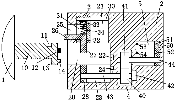
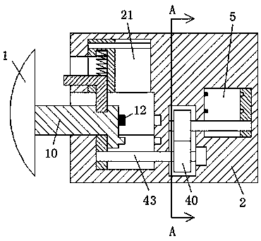
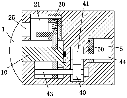
[0021] refer to Figure 1-4 As shown, a firmly locked LED lamp of the present invention includes a frame body 2 installed on an indoor wall and a lamp body 1 for cooperating with the frame body 2, and the left end surface of the frame body 2 is provided with Insertion slot 20, a power supply hole 22 is provided at the lower position in the middle of the right end wall of the insertion slot 20, a first slide slot 21 is provided on the top end wall of the insertion slot 20, and a first sliding slot 21 is provided on the bottom end wall of the insertion slot 20. The second sliding groove 23 opposite to the first sliding groove 21 is provided with an...


PUM


Abstract

The invention discloses an LED lamp capable of being firmly locked. The LED lamp comprises a frame body installed on an indoor wall and a lamp body used for being in matched connection with the framebody. The LED lamp is characterized in that the left end face of the frame body is provided with an inserting groove, the lower position of the middle of the right end wall of the inserting groove isprovided with a power supply hole, the top end wall of the inserting groove is provided with a first sliding groove, and the bottom end wall of the inserting groove is provided with a second sliding groove opposite to the first sliding groove. The lamp body is firmly locked, and the lamp body can be powered on safely and stably. In the installation process, the lamp body is powered on while beinglocked. In the detaching process, the lamp body is unlocked while being powered off. The whole device is easy and convenient to operate, lamp body locking stability is greatly improved, the installation and detaching efficiency of the lamp body is improved, electric shock accidents are effectively prevented when the lamp body is installed and detached, and life safety of workers is ensured.

Description

technical field [0001] The invention relates to the technical field of LEDs, in particular to a securely locked LED lamp. Background technique [0002] LED lamps generally use LED as the light source, and they are mostly installed on indoor walls. The existing LED lamps are widely used because of their high luminous efficiency, low power consumption, long life, easy control, energy saving and environmental protection, etc., but the existing LED lamps are fixed on the indoor wall by screws or bolts during the installation process. This installation method will not only cause damage to the indoor wall, but also the installation operation is more cumbersome, which is not convenient for the rapid installation and disassembly of LED lamps. It is easy to loose during the use process, and the existing LED lamps are installed after the LED lamps are energized first, and then fixed. This installation sequence is likely to cause electric shock accidents during the installation of the ...

Claims


Application Information

Patent Timeline
Patent Type & Authority Applications(China)
IPC IPC(8): F21S8/00F21V19/00F21V21/002F21V23/06F21V25/00F21Y115/10
CPCF21S8/035F21V19/0025F21V21/002F21V23/06F21V25/00F21Y2115/10
Inventor 楼华
Owner 苏州瑞非通信息科技有限公司
Why Eureka
Try Eureka