Ultra-low quiescent dissipation LDO circuit and ultra-low quiescent dissipation LDO circuit for driving heavy load
A static power consumption, ultra-low technology, applied in the field of DC-DC devices, can solve problems such as affecting the service life of the circuit, the LDO circuit cannot operate normally, and the demand for LDO increasing, so as to prolong the service life, ensure stability, and effectively discharge. effect of current
- Summary
- Abstract
- Description
- Claims
- Application Information
AI Technical Summary
Problems solved by technology
Method used
Image

Examples
Embodiment 1
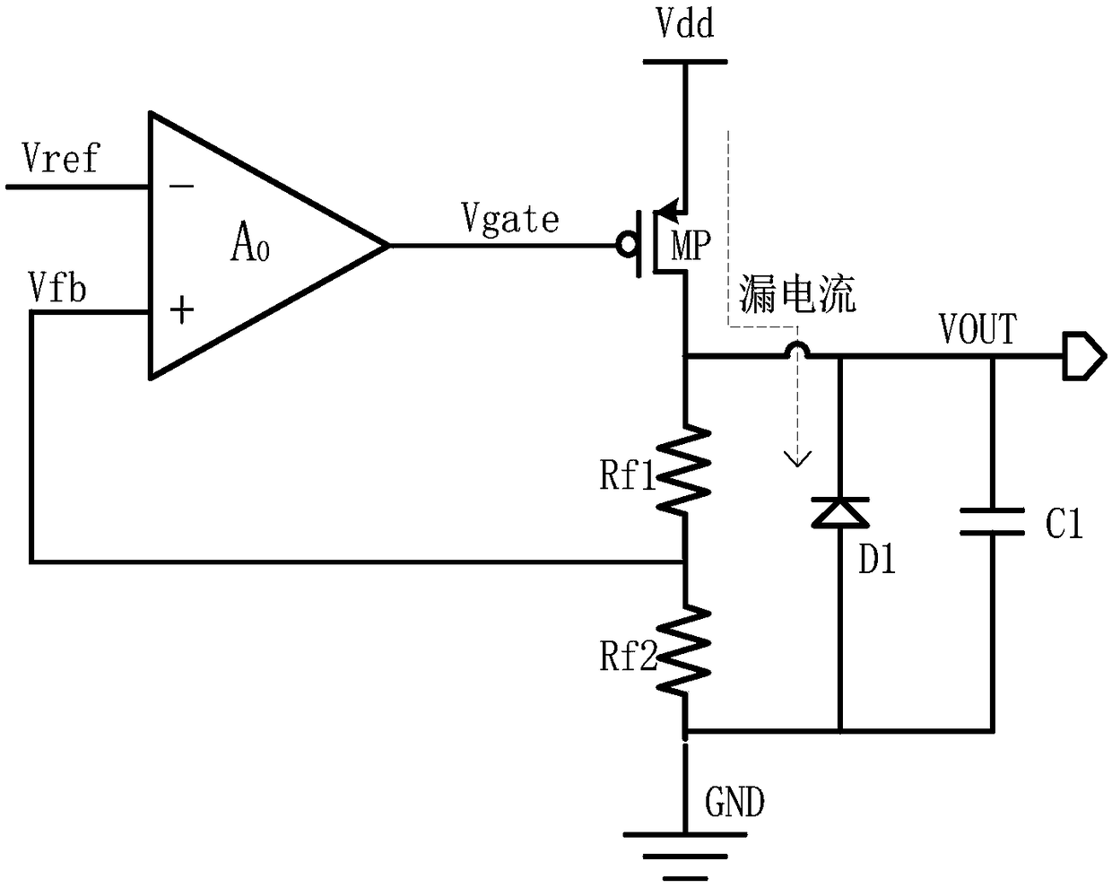
[0030] Such as figure 1 An ultra-low static power consumption LDO circuit is shown, including:
[0031] The voltage output terminal is used to output the modulated stable voltage;
[0032] The power transistor loop module connected to the power supply, and the power transistor loop module is connected to the voltage output terminal;
[0033] a grounded resistive feedback loop module, and the resistive feedback loop module is also connected to the power transistor loop module;
[0034] The gain amplifier module connected to the reference voltage, and the gain amplifier module is also connected with the resistance feedback loop module and the power transistor module. Optionally, the gain amplifier module is an amplifier;
[0035] The leakage current absorption module is grounded, and the leakage current absorption module is also connected to the power transistor loop module. Preferably, the leakage current absorption module is a reverse diode.
[0036] The working principle o...
Embodiment 2
[0038] This embodiment is based on the technical solution described in the first embodiment, and is further explained and supplemented.
[0039] In this embodiment, the leakage current absorbing module may include more than one reverse diode according to actual needs. Further, in order to increase the area of the leakage current absorbing module and further enhance the ability to absorb leakage current, each reverse diode can be connected in parallel to the circuit. Specifically, one end of the parallel circuit is grounded, and the other end is connected to the power transistor loop module . At no load, the leakage current will be along the figure 1 The direction indicated by the dotted line flows to the reverse diode, so that the LDO circuit described in this embodiment plays the role of discharging the quiescent current, thereby ensuring the stability of the voltage and prolonging the service life.
Embodiment 3
[0041] This embodiment is based on the technical solutions described in Embodiment 1 and Embodiment 2, and is further explained and supplemented.
[0042] Such as figure 1 As shown, in this embodiment, the gain amplifier module is a comparative amplifier, one input terminal is connected to the reference voltage, the other input terminal is connected to the feedback loop module, and the output terminal of the comparative amplifier is connected to the leakage current absorption module.
[0043] In this embodiment, the power transistor loop module is a series-connected adjustment transistor or a metal-oxide-semiconductor field-effect transistor (MOSFET).
[0044] In this embodiment, the resistor feedback loop module includes resistors Rf1 and Rf2 connected in series, wherein Rf1 is connected to the power transistor loop module, Rf2 is grounded, and the gain amplifier module is connected between Rf1 and Rf2.
[0045] In this embodiment, the voltage output terminal is connected to...
PUM
 Abstract
Description
Claims
Application Information
 - R&D Engineer
- R&D Manager
- IP Professional
- Industry Leading Data Capabilities
- Powerful AI technology
- Patent DNA Extraction
Browse by: Latest US Patents, China's latest patents, Technical Efficacy Thesaurus, Application Domain, Technology Topic.
© 2024 PatSnap. All rights reserved.Legal|Privacy policy|Modern Slavery Act Transparency Statement|Sitemap