
Aero-engine

A technology of aero-engines and moving blades, which is applied in the direction of engine components, machines/engines, mechanical equipment, etc. It can solve the problems that friction braking cannot continue, affect the effect of low-pressure turbine rotor speed limitation, and achieve the effect of reducing speed

Pending Publication Date: 2022-08-02
AECC COMML AIRCRAFT ENGINE CO LTD
View PDF0 Cites 2 Cited by
  • Summary
  • Abstract
  • Description
  • Claims
  • Application Information

AI Technical Summary

Problems solved by technology

However, after the low-pressure turbine rotor moves backward and collides with the stator structure, a collision force opposite to the axial force is generated, the rotor may bounce back, and friction braking cannot continue, which further affects the speed limitation effect of the low-pressure turbine rotor after the low-pressure shaft fails.

Method used


Image

  • Aero-engine
  • Aero-engine
  • Aero-engine

Examples


Embodiment Construction

[0024] The technical solutions in the embodiments of the present invention will be clearly and completely described below with reference to the accompanying drawings in the embodiments of the present invention. Obviously, the described embodiments are only a part of the embodiments of the present invention, but not all of the embodiments. The following description of at least one exemplary embodiment is merely illustrative in nature and is in no way intended to limit the invention, its application, or uses. Based on the embodiments of the present invention, all other embodiments obtained by those of ordinary skill in the art without creative efforts shall fall within the protection scope of the present invention.

[0025] The relative arrangement of the components and steps, the numerical expressions and numerical values ​​set forth in these embodiments do not limit the scope of the invention unless specifically stated otherwise. Meanwhile, it should be understood that, for th...


PUM


Abstract

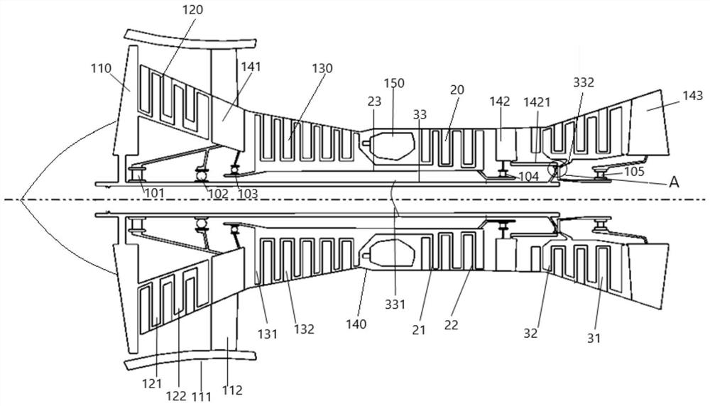
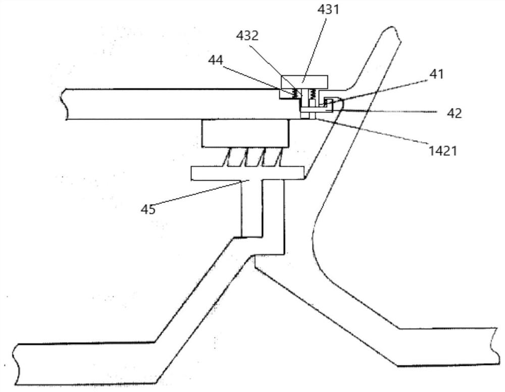
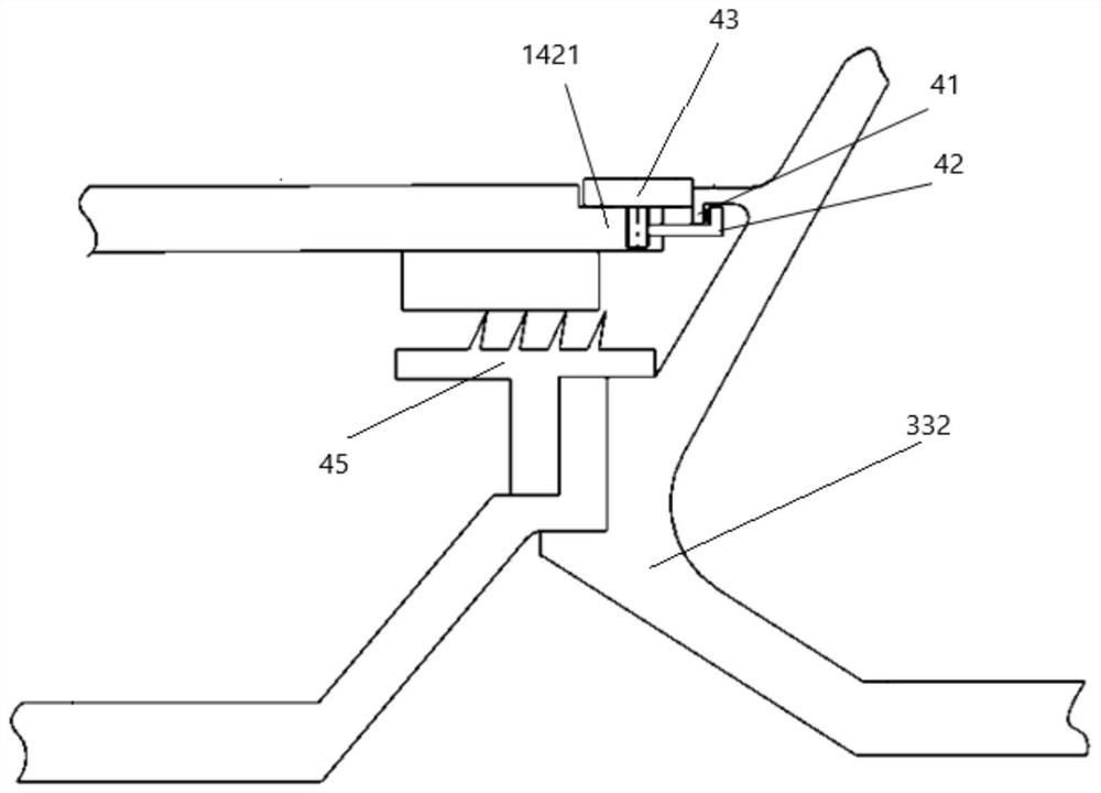
The invention discloses an aero-engine which comprises a turbine, the turbine comprises a rotor and a stator, the aero-engine further comprises a shaft failure speed limiting device arranged between the rotor and the stator, and the shaft failure speed limiting device comprises a pulling part fixedly connected to the rotor; the distance piece is arranged on the stator; the locking piece is arranged on the stator; the shaft failure speed limiting device is configured in the mode that when a turbine works normally, a locking piece is located at a locking piece first position relative to a stator, a spacing part of a spacing piece is kept at a spacing part first position relative to the stator, and gaps are kept between a pulling part and the locking piece and between the pulling part and the spacing piece; when a turbine shaft failure working condition occurs in the turbine and a movable blade of the turbine moves towards the downstream of the gas flowing direction in the axial direction, the pulling part pulls the locking piece to move towards the downstream of the gas flowing direction in the axial direction to the locking piece second position, the spacing part of the spacing piece moves to the spacing part second position, and at the spacing part second position, the movable blade of the turbine moves towards the downstream of the gas flowing direction in the axial direction. The spacing part is located on the upstream of the pulling part and located between the pulling part and the stator in the axial direction.

Description

technical field [0001] The invention relates to the field of aviation machinery, in particular to an aero-engine. Background technique [0002] In actual operation of turbine-driven engines, turbine shaft failure may occur due to overtorque, resonance, fatigue, corrosion, material defects and manufacturing errors or other indirect events. Although the probability of turbine shaft failure is small, the failure of the turbine shaft Once it occurs, it may lead to harmful consequences. For example, in an aero-engine, when the turbine shaft fails, the rotor of the turbine is decoupled from the front-end load (compressor), and at the same time, driven by the high-energy gas discharged from the combustion chamber, the rotational speed increases instantaneously, or enters an overspeed rotation state. When the rotational speed rises to a certain level , the disc stress reaches a critical level and rupture occurs, and the ruptured high-energy debris has the risk of penetrating the en...

Claims


Application Information

Patent Timeline
Patent Type & Authority Applications(China)
IPC IPC(8): F01D5/02F01D5/14F01D9/02F02C9/00F01D11/00
CPCF01D5/02F01D5/14F01D9/02F02C9/00F01D11/003
Inventor 龚煦翁依柳郑李鹏
Owner AECC COMML AIRCRAFT ENGINE CO LTD
Learn More