Supercharge Your Innovation With Domain-Expert AI Agents!

Method for debugging optical axis parallelism of multiple optical devices

An optical device, optical axis-parallel technology, applied in the parts and instruments of the instrument, can solve the problems of investing a lot of money, expensive large-diameter collimator, increasing production cost, etc., to improve efficiency, reasonable design, and economical cost effect

Inactive Publication Date: 2018-05-22
TIANJIN NAVIGATION INSTR RES INST
View PDF7 Cites 1 Cited by
  • Summary
  • Abstract
  • Description
  • Claims
  • Application Information

AI Technical Summary

Problems solved by technology

The traditional method in the past is to use a large-diameter collimator (the caliber is required to include both the TV camera and the laser range finder) to adjust the parallelism of the optical axis between the two, but the price of the large-diameter collimator is very expensive. The instrument needs to invest a lot of money, which increases the production cost

Method used


Image

  • Method for debugging optical axis parallelism of multiple optical devices
  • Method for debugging optical axis parallelism of multiple optical devices

Examples


Embodiment Construction

[0017] The embodiments of the present invention will be described in detail below in conjunction with the accompanying drawings. It should be noted that the embodiments are illustrative, not restrictive, and cannot limit the protection scope of the present invention.

[0018] A method for adjusting the parallelism of optical axes of multiple optical devices, comprising the following steps:

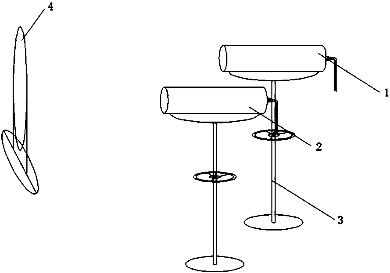
[0019] (1) Place the plane mirror 4 on the large flat plate of the static base, and place two liftable collimator brackets 3 at a distance of 2-4m from the plane mirror, and install a collimator on each collimator bracket. According to the installation positions of the TV camera and the laser range finder, adjust the relative positions of the two collimators to be consistent with the relative positions of the TV camera and the laser range finder to be adjusted.

[0020] ⑵. Turn on the power of the No. 1 collimator, observe the cursor image returned by the plane mirror from the No. 1 collim...


PUM


Abstract

A method for debugging the optical axis parallelism of multiple optical devices is designed. Two low-cost collimators are used to substitute a large-diameter collimator, and the parallelism debuggingbetween optical axes of a television camera and a laser rangefinder is completed smoothly. By using the method, the parallelism debugging between the two optical axes of the television camera and thelaser rangefinder can be achieved, the cost is saved, the efficiency is improved, and at the same time, the method can be promoted and applied in optical axis debugging of other optical devices.

Description

technical field [0001] The invention relates to the technical field of azimuth extraction devices, in particular to a method for adjusting the parallelism of optical axes of multiple optical devices. Background technique [0002] The azimuth extraction device is the main equipment of a certain type of artillery tracked command vehicle. It is used for the joint measurement of the artillery position battle formation, assigning the artillery reference direction, and real-time observation and monitoring of the battlefield and ground target determination. [0003] The device is composed of a device main body, a control box and a joystick. The main body of the device is equipped with a TV camera and a laser range finder. The image recorded by the TV camera can be displayed on the command terminal computer. After the target is selected by the joystick, the laser range measurement is performed on the target. If the parallelism between the two optical axes of the TV camera and the la...

Claims


Application Information

Patent Timeline
IPC IPC(8): G12B5/00
CPCG12B5/00
Inventor 屈建龙史英桂颜苗罗巍赵爱武
Owner TIANJIN NAVIGATION INSTR RES INST
Features
  • R&D
  • Intellectual Property
  • Life Sciences
  • Materials
  • Tech Scout
  • Unparalleled Data Quality
  • Higher Quality Content
  • 60% Fewer Hallucinations
Learn More