Radio frequency filter and method for tuning same

A filter and radio frequency technology, applied in tunable filters, filters, waveguide devices, etc., can solve the problems of increasing filter insertion loss, increasing the number of resonators, and large three-dimensional tuning structures

Active Publication Date: 2018-05-22
MURATA MFG CO LTD
View PDF20 Cites 4 Cited by
  • Summary
  • Abstract
  • Description
  • Claims
  • Application Information

AI Technical Summary

Problems solved by technology

While this prior art technique has been generally successful in tuning the frequency band, it inevitably introduces resistance into the resonator, which adversely increases the insertion loss of the filter
[0013] Although it is possible to tune an HTS filter to change its resonant frequency by mechanically moving the HTS plate on each resonator in the filter without introducing significant resistance to the resonators, this technique is inherently slow (in seconds order of magnitude) and requires a relatively large three-dimensional tuning structure
Insertion loss can be reduced in so-called switched filter designs; however, these designs still introduce a significant amount of loss between switching times and require additional resonator
For example, the insertion loss of the filter system can be reduced by having two filters and a pair of single-pole double-throw switches (SP2T) that select between the filters, effectively reducing the tuning range requirement, but increasing the number of resonators by a factor of two and introduce losses from the switch
The loss of the filter system can be further reduced by introducing more switches and filters, but each additional filter will require the same number of resonators as the original filter, and more losses will be introduced by the required switches

Method used


Image

  • Radio frequency filter and method for tuning same
  • Radio frequency filter and method for tuning same
  • Radio frequency filter and method for tuning same

Examples


Embodiment Construction

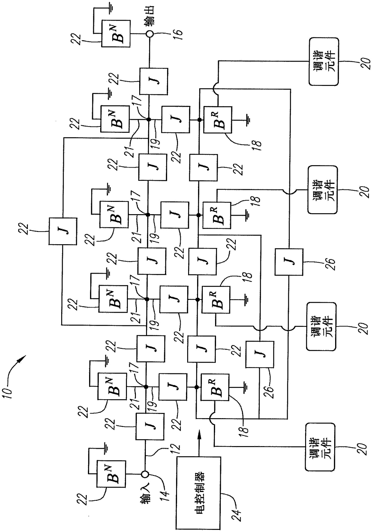
[0055] refer to figure 1 , a tunable radio frequency (RF) filter 10 constructed in accordance with the present invention will now be described. In the illustrated embodiment, the RF filter 10 is a bandpass filter with a passband tunable within a desired frequency range, such as 800MHz-900MHz or 1,800MHz-2,220MHz. In a typical scenario, the RF filter 10 is placed in the front end of a receiver (not shown) after a wide passband filter that rejects energy outside the desired frequency range. The RF filter 10 generally includes a signal transmission path 12 having an input 14 and an output 16, a plurality of nodes 17 arranged along the signal transmission path 12, a plurality of resonant branches 19 respectively extending from the nodes 17, and a plurality of resonant branches respectively extending from the nodes 17. A plurality of non-resonant branches 21 . The RF filter 10 further comprises a plurality (in this case four) of resonant elements 18 between the input 14 and the o...


PUM


Abstract

The invention discloses a radio frequency filter and a method for tuning the same. The RF filter comprises a signal transmission path having an input and an output, a plurality of resonant elements disposed along the signal transmission path between the input and the output, and a plurality of non-resonant elements coupling the resonant elements together to form a stop band having a plurality of transmission zeroes corresponding to respective frequencies of the resonant elements, and at least one sub-band between the transmission zeroes. The non-resonant elements comprise at least one variablenon-resonant element for selectively introducing at least one reflection zero within the stop band to create a pass band in a selected one of the sub-band(s), wherein the stop band is in a microwavefrequency range.

Description

[0001] This application is a divisional application of an invention patent application with an application date of December 31, 2014, an application number of 201410854568X, and an invention titled: low-loss tunable radio frequency filter. [0002] Cross References to Related Applications [0003] This application is a continuation-in-part of U.S. Patent Application Serial No. 13 / 282,289, filed October 26, 2011, which was filed December 2, 2010, now issued as U.S. Patent No. 8,063,714 Continuation of U.S. Patent Application Serial No. 12 / 959,237, U.S. Patent Application Serial No. 12 / 959,237 is a continuation of U.S. Patent Application Serial No. 12 / 620,455, filed November 17, 2009, now issued as U.S. Patent No. 7,863,999, U.S. Patent Application Serial No. 12 / 620,455 is a continuation of U.S. Patent Application Serial No. 12 / 163,814 filed June 27, 2008, now issued as U.S. Patent No. 7,639,101, which claims June 27, 2007 Priority to U.S. Provisional Patent Application Serial No...

Claims


Application Information

Patent Timeline
IPC IPC(8): H03H7/12
CPCH01P1/20H01P1/20336H03H7/0153H03H7/0161H03H7/075H03H7/12H03H7/1758H03H7/1791H03H7/54H03H2007/013H03H2009/02204H03H2210/012H03H2210/025H03H2210/033Y10T29/49018H03H7/03H03H9/171H03H2009/02173G06F30/392G06F30/367G06F2119/10G06F30/394G06F2111/06G06F2111/20G06F30/36G06F2111/10G06F30/30H03H3/00H03H7/06H03H9/46H03H9/462H03H9/465H03H9/542H03H9/64H03H9/6406
Inventor 格尼希·楚祖基巴拉姆·A·威廉森
Owner MURATA MFG CO LTD
Why Eureka
Try Eureka