
No-reflection bandpass low-pass filter based on transmission wire structure

A technology of transmission line structure and low-pass filter, which is applied to waveguide devices, electrical components, circuits, etc., can solve the problems of low operating frequency and inapplicability of radio frequency and microwave frequency bands of non-reflection filters, and achieves simple structure and easy processing and production Effect

Active Publication Date: 2018-04-13
NANJING UNIV OF POSTS & TELECOMM
View PDF5 Cites 7 Cited by
  • Summary
  • Abstract
  • Description
  • Claims
  • Application Information

AI Technical Summary

Problems solved by technology

[0004] The technical problem to be solved by the present invention is to provide a non-reflection band stop and low-pass filter based on the transmission line structure to solve the problem that the existing non-reflection filter has a low operating frequency and is not suitable for the defects involved in the background technology. RF Microwave Band Problems

Method used

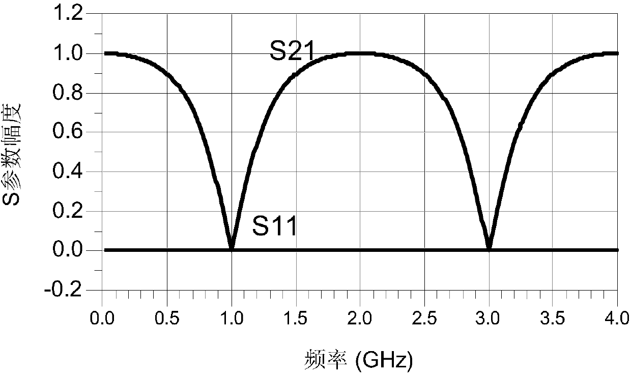
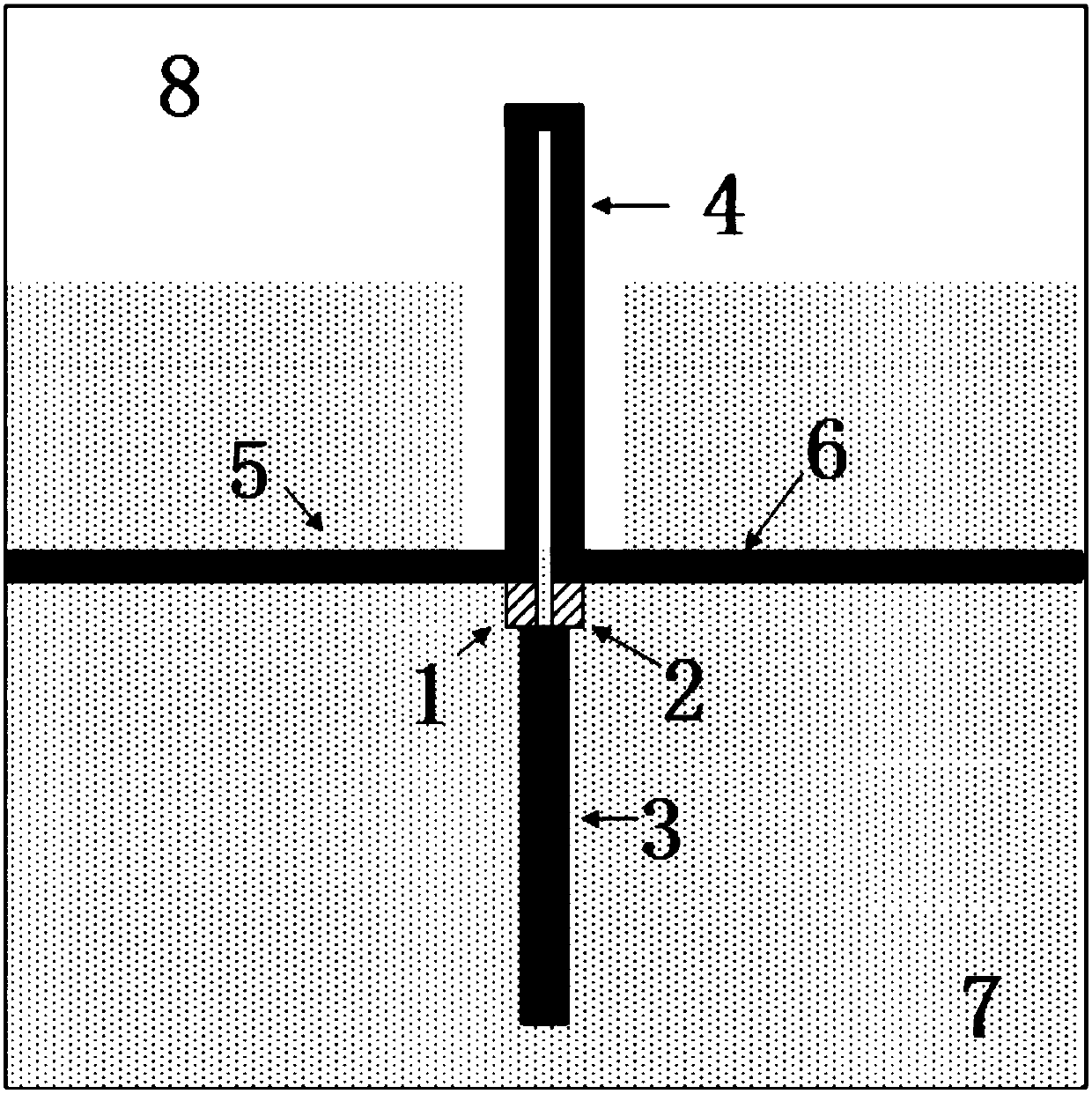

Image

  • No-reflection bandpass low-pass filter based on transmission wire structure
  • No-reflection bandpass low-pass filter based on transmission wire structure
  • No-reflection bandpass low-pass filter based on transmission wire structure

Examples


Embodiment Construction

[0024] Below in conjunction with accompanying drawing, technical scheme of the present invention is described in further detail:

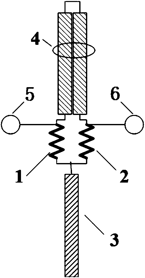
[0025] Such as figure 1 As shown, the present invention discloses a non-reflection band-stop and low-pass filter based on a transmission line structure, including a first absorption resistor, a second absorption resistor, an open terminal transmission line section, a terminal short circuit transmission line section, an input port and an output port;

[0026] One end of the first absorbing resistor is respectively connected to one end of the second absorbing resistor and one end of the open-terminated transmission line section, and the other end is respectively connected to an input port and an end point on one side of the terminal short-circuited transmission line section;

[0027] The other end of the second absorbing resistor is respectively connected to the output port and the other terminal on one side of the short-circuited transmission line n...


PUM


Abstract

The invention discloses a no-reflection bandpass low-pass filter based on a transmission wire structure. The no-reflection bandpass low-pass filter comprises two absorbing resistors, a quarter wavelength terminal open end transmission line segment, a quarter wavelength terminal short-circuit transmission line segment and two input / output ports. The two absorbing resistors are placed in a close manner, The absorbing resistor is provided with one common end point and two independent end points. The quarter wavelength terminal open end transmission line segment is connected between the common endpoints of the two absorbing resistors. Two end points of the quarter wavelength terminal open end transmission line segment are respectively connected with the two independent end points of the two absorbing resistors. The two input / output ports are respectively connected with the independent end points of the two absorbing resistors. Through reasonably setting the resistance of each element, theno-reflection transmission wire type filter can be obtained, a bandpass and low-pass filtering function can be realized. The no-reflection bandpass low-pass filter is suitable for filter circuit realization in a microwave frequency range, and furthermore has advantages of low cost, easy machining property, stable performance, etc.

Description

technical field [0001] The invention relates to the technical field of microwave radio frequency circuits, in particular to a non-reflection band stop and low pass filter based on a transmission line structure. Background technique [0002] A filter is an electronic device that is widely used in various electronic systems. The device generally has two ports that allow electrical signals in the passband to pass through without loss or with low loss, while prohibiting electrical signals in the stopband from being transmitted between the two ports. [0003] Existing filters are generally reflective. According to the law of energy conservation, if the input electrical signal at the input terminal is within the passband, it will be transmitted to the output terminal; when the input signal is within the stop band, it will be totally reflected to the input terminal, and there will be no signal output at the output terminal at this time. If the power of the reflected signal is lar...

Claims


Application Information

Patent Timeline
Patent Type & Authority Applications(China)
IPC IPC(8): H01P1/203
CPCH01P1/203
Inventor 金秀华黄晓东
Owner NANJING UNIV OF POSTS & TELECOMM
Learn More