Backlight module lens and backlight module lens comprising backlight module lens

A technology of backlight module and lens, applied in the field of backlight, to achieve the effect of uniform distribution of light effect

Inactive Publication Date: 2018-05-22
OPTIKA SUZHOU OPTO ELECTRONICS
View PDF6 Cites 2 Cited by
  • Summary
  • Abstract
  • Description
  • Claims
  • Application Information

AI Technical Summary

Problems solved by technology

Taking a 75-inch panel as an example, the pixel density of the 4K panel is only 59ppi. If it is increased to 8K, the PPI can be increased to more than 110, and the fineness of the display screen will be greatly improved.

Method used


Image

  • Backlight module lens and backlight module lens comprising backlight module lens
  • Backlight module lens and backlight module lens comprising backlight module lens
  • Backlight module lens and backlight module lens comprising backlight module lens

Examples


Embodiment 1

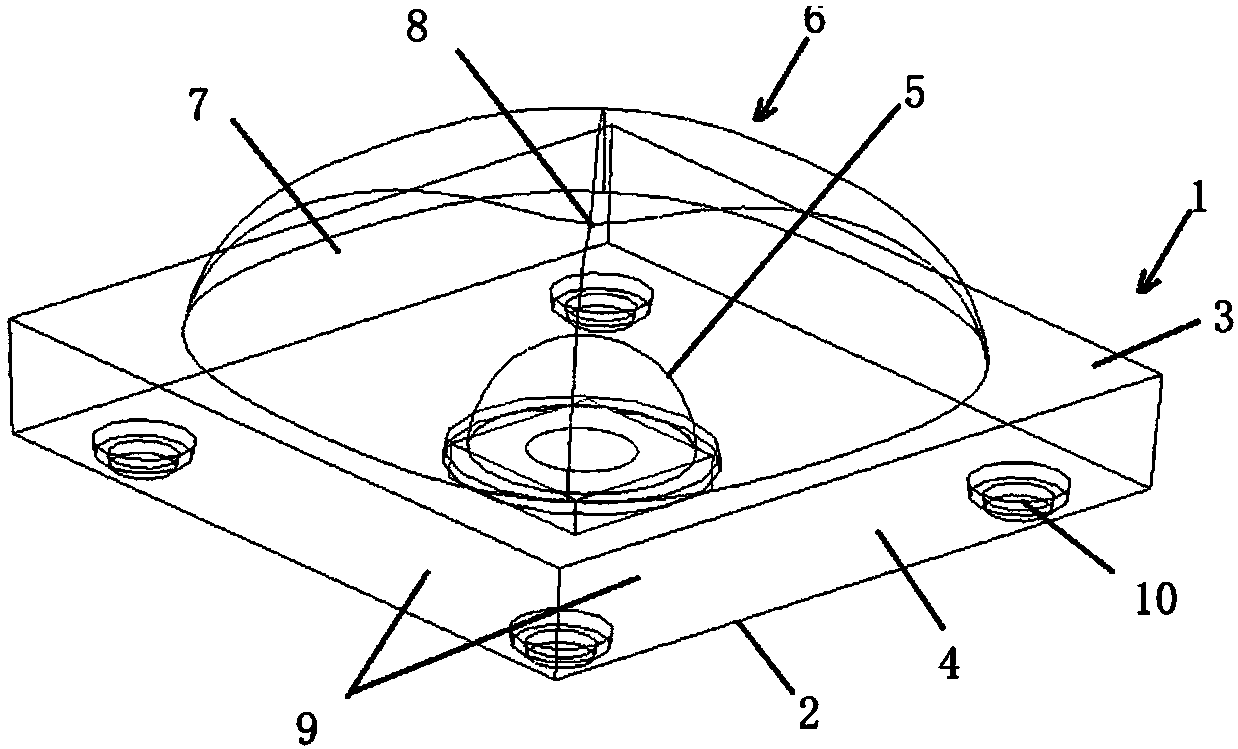
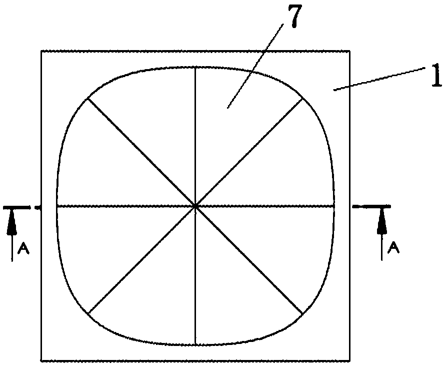
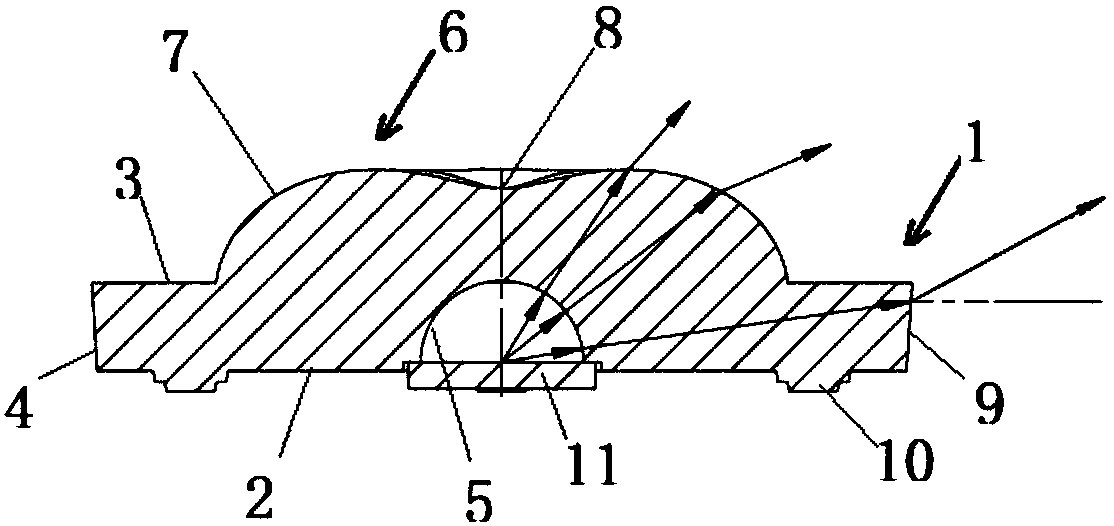
[0031] see attached figure 1 to attach Figure 4 As shown, the backlight module lens in this embodiment is made of glass or optical resin material. The base 1 has a cubic structure as a whole. The base 1 has a square bottom surface 2, a square top surface 3, and side surfaces 4. The bottom surface 2 is provided with positioning columns 10 for installation and positioning. The center of the bottom surface 1 is depressed upward to form a light incident surface 5.

[0032] The top surface 3 bulges upwards to form the main light-emitting surface 6. The main light-emitting surface 6 includes four free-form surfaces 7 spliced ​​together. The four free-form surfaces 7 have a joint center point 8 and are symmetrical around the joint center point 8. The joint center point 8 Recessed downward toward the light-incident surface 5 and located on the same center line as the center point of the light-incident surface 5, wherein the size of the bottom surface 2 of the substrate 1 is smaller ...

Embodiment 2

[0036] see attached Figure 5 to attach Figure 8 As shown, the backlight module lens in this embodiment is made of glass or optical resin material. The base 1 has a cubic structure as a whole. The base 1 has a square bottom surface 2 with rounded corners, a square top surface 3 with rounded corners, and side surfaces 4. The positioning column 10 is used for installation and positioning, and the center of the bottom surface 1 is recessed upward to form the light incident surface 5 .

[0037] The top surface 3 bulges upwards to form the main light-emitting surface 6. The main light-emitting surface 6 includes four free-form surfaces 7 spliced ​​together. The four free-form surfaces 7 have a joint center point 8 and are symmetrical around the joint center point 8. The joint center point 8 It is recessed downward toward the light incident surface 5 and is located on the same center line as the center point of the light incident surface 5, wherein the size of the bottom surface ...


PUM

PropertyMeasurementUnit
radiusaaaaaaaaaa

Abstract

The invention discloses a backlight module lens. The lens comprises a substrate having a cubic structure as a whole; the substrate comprises a square bottom surface, a square top surface and a side surface, wherein a center of the bottom surface is recessed upward to form a light incident surface; the top surface upwardly bulges in order to form a main light-emitting surface, and the main light exiting surface comprises four free curved surfaces, and the four free curved surfaces have a combined center point and are symmetric about the center of the combined center point; and the combined center point is downward recessed toward to the light incident surface and is on the same center line as the center point of the light-incident surface, wherein the bottom surface of the substrate has a size smaller than the top surface size such that the side surface is inclined toward the inner side by an angle theta 1 to form an auxiliary light-emitting surface. The backlight module lens can outputa square spot with clear edges, and can achieve uniform illumination distribution in the projection area, and the overall illumination effect is excellent when combined into an array.

Description

technical field [0001] The invention relates to an optical lens for converting a point light source into a surface light source, which is suitable for general lighting, especially the technical field of backlight. Background technique [0002] With the development of large-size LCD TV technology, the backlight of LCD TV requires a large number of LEDs to be arranged in an array to illuminate the LCD panel. A lens is arranged in front of each LED chip, and the light from the LED is reconverted through the lens. Light distribution to reduce the thickness of the backlight module and the amount of LED used, while meeting the requirements of brightness and uniformity of the LCD backlight. Currently on the market, most of the LED lenses on the market have a circular outline in the top view projection of the optical structure, and the shape of the optical structure is mostly in the form of rotational symmetry. TV displays are generally square, and it would be more reasonable to us...

Claims


Application Information

Patent Timeline
Patent Type & Authority Applications(China)
IPC IPC(8): G02F1/13357
CPCG02F1/133603G02F1/133605G02F1/133606G02F1/133607
Inventor 刘海生刘龙辉
Owner OPTIKA SUZHOU OPTO ELECTRONICS
Why Eureka
Try Eureka