Reflecting film and backlight module

A technology of backlight module and reflective film, applied in optics, nonlinear optics, instruments, etc., can solve the problems of inaccessible light, dark areas in the corners of reflective films, etc.

Inactive Publication Date: 2017-09-15
BOE TECH GRP CO LTD +1
View PDF8 Cites 0 Cited by
  • Summary
  • Abstract
  • Description
  • Claims
  • Application Information

AI Technical Summary

Problems solved by technology

[0003] The invention provides a reflective film and a backlight module to solve the problem of dark areas appearing in the corners of the reflective film because light cannot reach the corners of the reflective film

Method used


Image

  • Reflecting film and backlight module
  • Reflecting film and backlight module
  • Reflecting film and backlight module

Examples


Embodiment 1

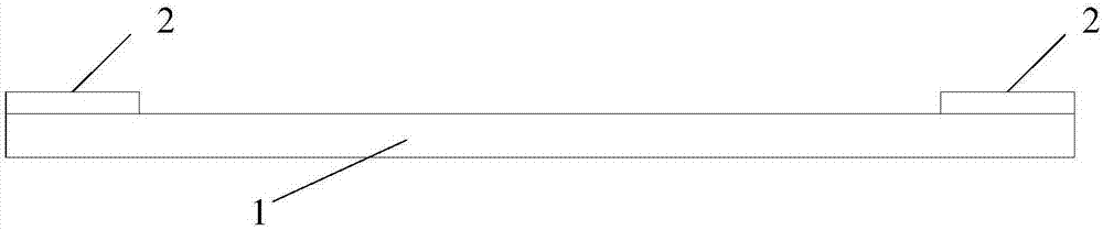
[0021] Reference figure 2 , Which shows a schematic structural diagram of a reflective film according to the first embodiment of the present invention.

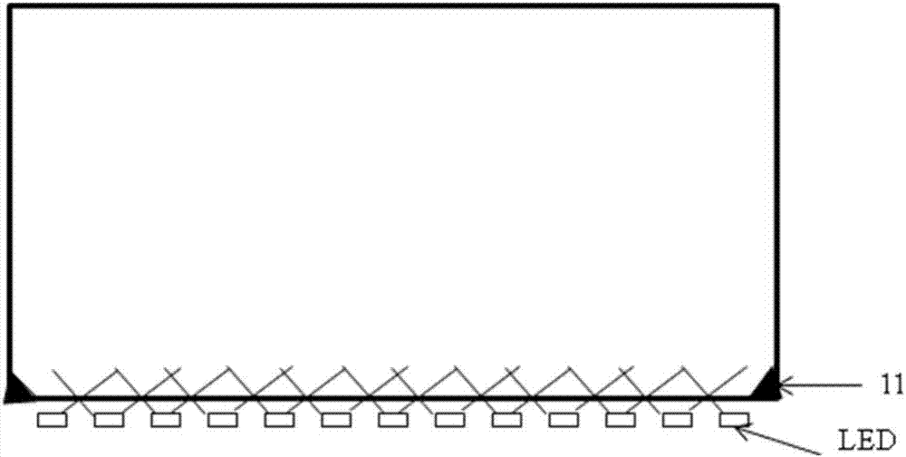
[0022] The reflective film 1 is applied to a backlight module, the light source of the backlight module has a dark area formed on the reflective film 1, and the reflective film is coated with a thermoluminescent material 2 at the dark area.

[0023] After a product design is determined, the dark area is also determined, that is, the area of ​​the generated dark area will not change, so the thickness of the thermoluminescent material 2 coating can be adjusted according to the dark area. Preferably, The coating thickness of the thermoluminescent material 2 is 20um-50um, which is not specifically limited in the present invention.

[0024] A thermoluminescent material solution is coated on the dark area of ​​the reflective film, and after a series of treatments, the thermoluminescent material solution is dried to form a thermoluminesce...

Embodiment 2

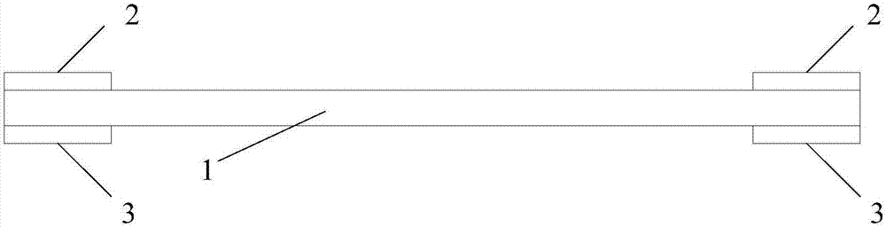
[0028] Reference image 3 , Which shows a schematic structural diagram of a reflective film according to the second embodiment of the present invention.

[0029] The reflective film 1 is applied to a backlight module, the light source of the backlight module has a dark area formed on the reflective film 1, and the reflective film is coated with a thermoluminescent material 2 on the front surface of the dark area. , The backside of the dark area is coated with an endothermic and heat accumulating material 3.

[0030] Because after a product design is determined, the area of ​​the dark area will not change. The thickness of the thermoluminescent material 2 and the endothermic heat gathering material 3 can be adjusted according to the dark area. Preferably, the The coating thickness of the thermoluminescent material 2 and the endothermic heat gathering material 3 is 20um-50um, which is not specifically limited in this application.

[0031] Apply a mixture of thermoluminescent material ...

Embodiment 3

[0042] The invention also discloses a backlight module, including the reflective film described in the first to second embodiments.

[0043] The backlight module has all the advantages of the reflective film in the first to second embodiments described above, and will not be repeated here.


PUM


Abstract

The invention provides reflecting film and a backlight module. The reflecting film is applied to the backlight module, the light source of the backlight module forms a dark region on the reflecting film, regarding the reflecting film, a thermoluminescence material is smeared on the dark region, and therefore the problem is solved that since light cannot reach the corner of the reflecting film, the dark region occurs at the corner of the reflecting film.

Description

Technical field [0001] The present invention relates to the technical field of liquid crystal display, in particular to a reflective film and a backlight module. Background technique [0002] In a liquid crystal display, such as figure 1 As shown, the light emitted by the backlight is reflected on the LCD screen through the reflective film. The backlight includes multiple LED lamps. Due to the large central moment between the two LED lamps, it is easy to cause the LED lights on the edge to fail to reflect the film. Direct illumination is performed, so that the light cannot directly reach the corners of the reflective film, and a dark area 11 appears at the corners of the reflective film, which affects the quality of the display screen of the liquid crystal display. Summary of the invention [0003] The present invention provides a reflective film and a backlight module to solve the problem of dark areas in the corners of the reflective film because light cannot reach the corners o...

Claims


Application Information

Patent Timeline
Patent Type & Authority Applications(China)
IPC IPC(8): G02F1/13357
CPCG02F1/133605G02F1/133611G02F1/133615
Inventor 曹杰王小丽胡宇飞唐书喜龚庸才
Owner BOE TECH GRP CO LTD
Why Eureka
Try Eureka