

Light guide plate and backlight module
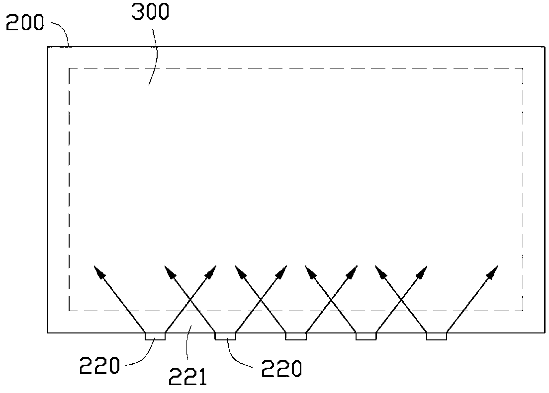
A technology of backlight module and light guide plate, which is applied in the direction of optics, light guide, electric light source, etc., and can solve the problem of uneven brightness distribution of the light output surface 300
- Summary
- Abstract
- Description
- Claims
- Application Information
AI Technical Summary
Problems solved by technology
Method used
Image

Examples
Embodiment Construction
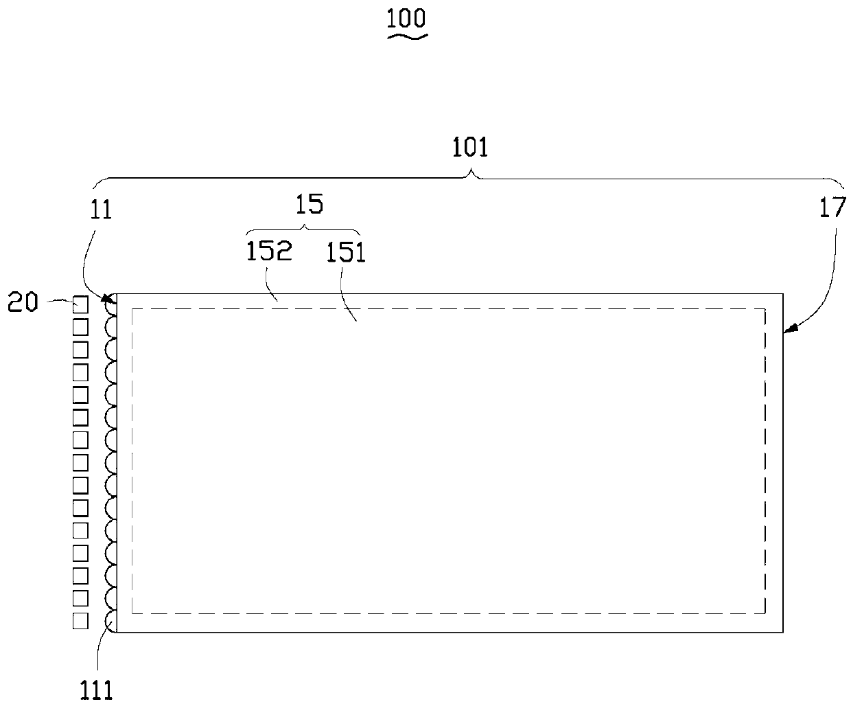
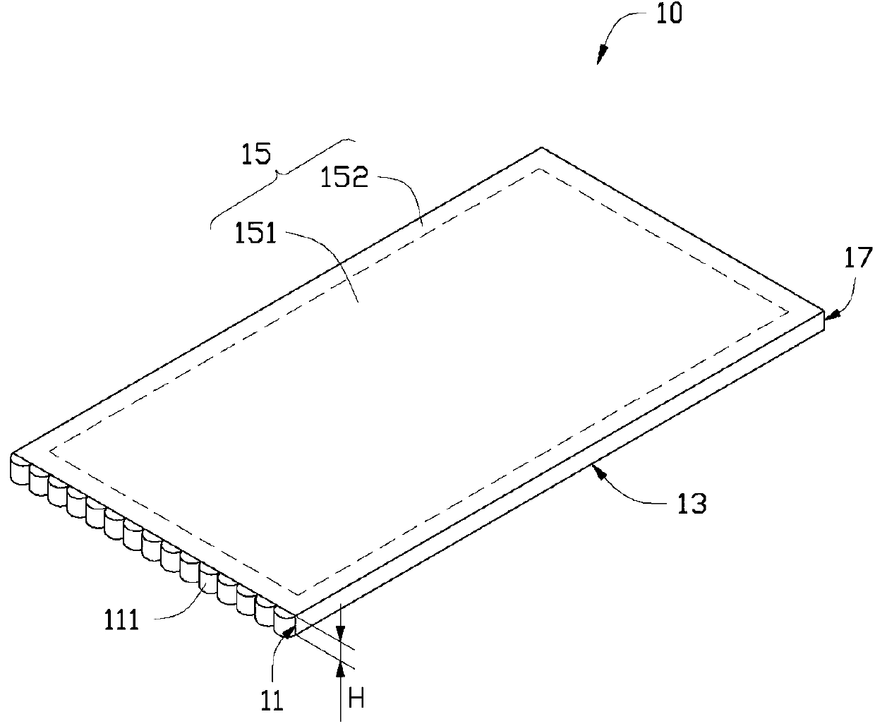
[0014] see figure 2 and image 3 , is a backlight module 100 provided in an embodiment of the present invention, which includes a light guide plate 10 and a plurality of light sources 20 . In this embodiment, the light source 20 is a light emitting diode (Light Emitting Diode, LED).
[0015] The light guide plate 10 includes a body 101 and a plurality of dots 111 . The body 101 is in the shape of a rectangular plate and is made of light-transmitting materials, such as acrylic resin, polycarbonate, polyethylene resin, and the like. The body 101 includes a light incident surface 11 , a back surface 13 , a front surface 15 and a side surface 17 . The light incident surface 11 and the side surface 17 are located on two opposite sides of the light guide plate 10 and are parallel to each other. The front surface 15 and the back surface 13 are located on opposite sides of the light guide plate 10 and are parallel to each other. The front surface 15 and the back surface 13 are c...
PUM
 Abstract
Description
Claims
Application Information