Liquid crystal display device

Inactive Publication Date: 2007-10-11
PANASONIC LIQUID CRYSTAL DISPLAY CO LTD
View PDF10 Cites 17 Cited by
  • Summary
  • Abstract
  • Description
  • Claims
  • Application Information

AI Technical Summary

Benefits of technology

[0012]According to the present invention, by focusing the light radiation direction from the light guide plate in the vertical direction with respect to the light radiation surface, a light utilization efficiency can be largel

Problems solved by technology

However, in the backlight which uses a plurality of LEDs for increasing the brightness as the light emitting element, a plurality of light emitting points exist and hence, positions and shapes of members which reflect and radiate the light passing through the inside of the light guide plate become complicated.
Particularly, when

Method used


Image

  • Liquid crystal display device
  • Liquid crystal display device
  • Liquid crystal display device

Examples


Embodiment Construction

[0028]The present invention is explained in detail in conjunction with specific embodiments using drawings showing the embodiments hereinafter.

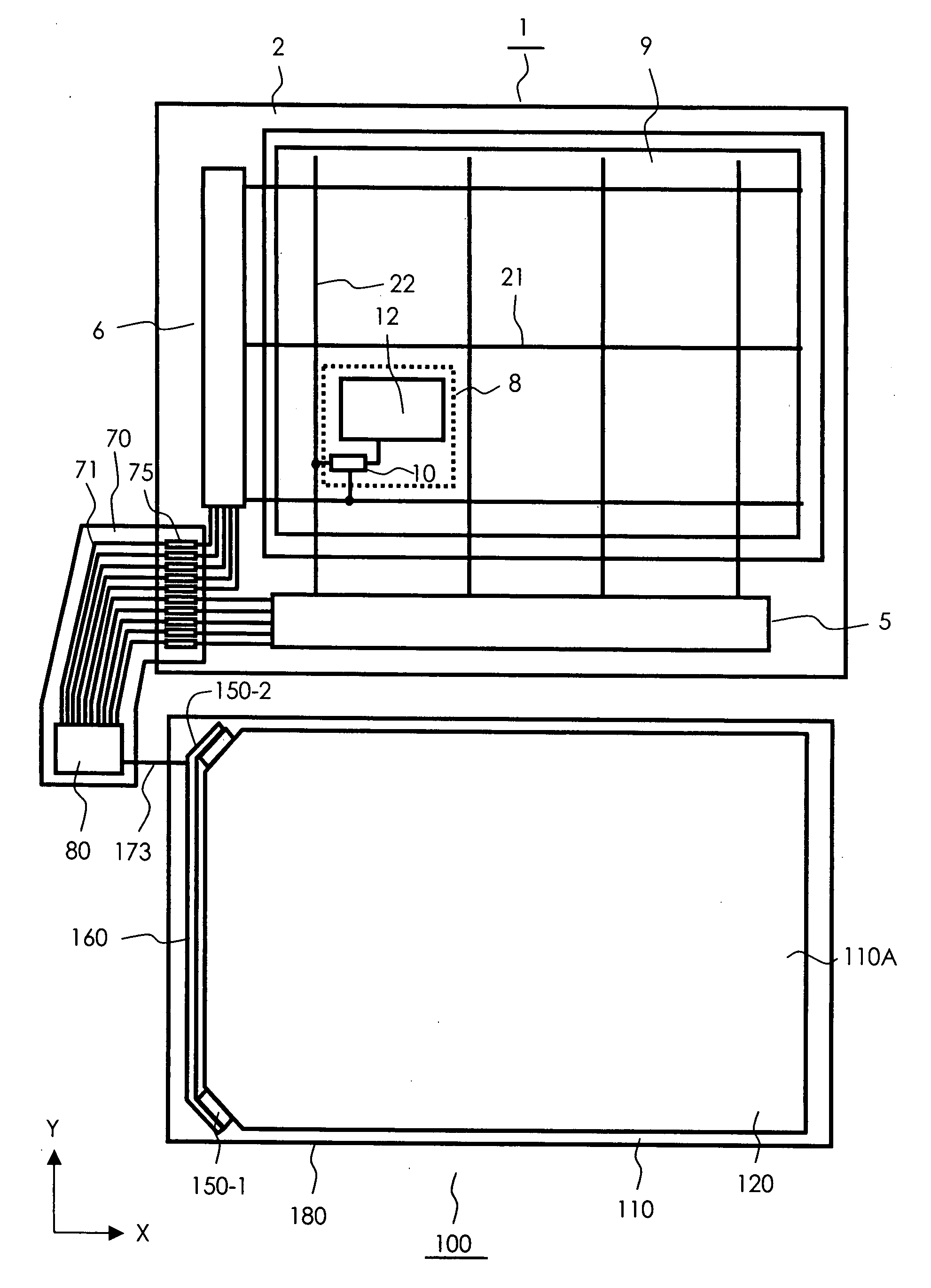
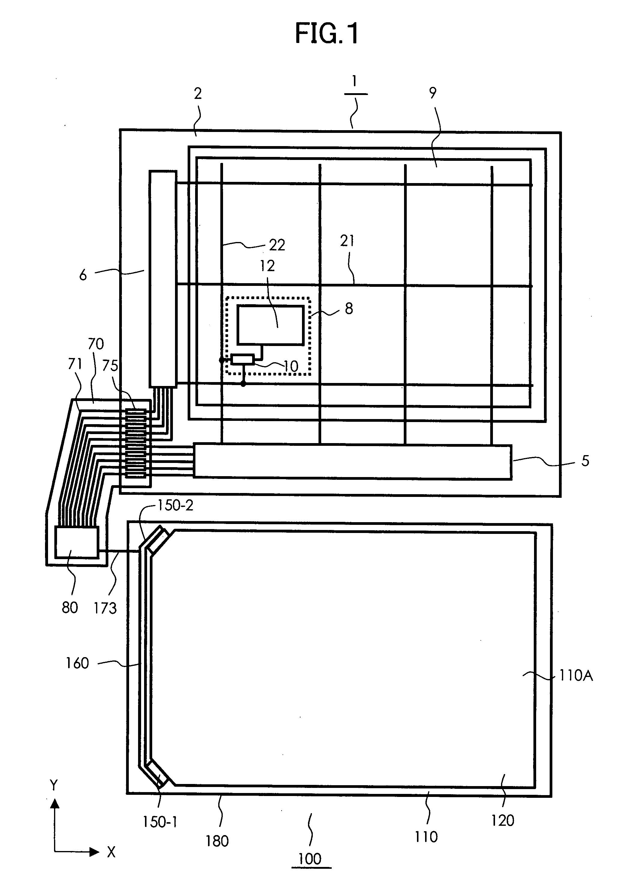
[0029]FIG. 1 is a plan view of an essential part showing the whole constitution according to one example of a liquid crystal display device of the present invention. In FIG. 1, the liquid crystal display device 100 is constituted of a liquid crystal display panel 1, a backlight 110 and a control circuit 80. The liquid crystal display panel 1 is formed by sealing a liquid crystal layer between glass substrates having electrodes for forming pixels. Signals and power source voltages necessary for display using liquid crystal are supplied to the liquid crystal display panel 1 from the control circuit 80. The control circuit 80 is mounted on a flexible printed circuit board 70, and control signals are supplied to the liquid crystal display panel 1 via a line 71 and terminals 75 of the flexible printed circuit board 70.

[0030]The backlight 110 is co...


PUM


Abstract

The present invention provides a liquid crystal display device of high quality having high brightness and uniform brightness distribution by focusing the light radiation direction from a light guide plate in the vertical direction with respect to a light radiation surface of the light guide plate. The liquid crystal display device includes a liquid crystal display panel and a flat lighting device which radiates an illumination light to a back surface of the liquid crystal display panel. The flat lighting device includes a light guide plate which has an upper surface facing a back surface of the liquid crystal display panel in an opposed manner and constituting a light radiation surface and a bottom surface which is arranged opposite to the upper surface. One LED is arranged at a first corner portion of the light guide plate and another LED is arranged at a second corner portion of the light guide plate arranged adjacent to the first corner portion. By forming reflection surfaces which are inclined toward the upper surface from the bottom surface of the light guide plate and inclined surfaces which abut on the reflection surfaces on the lower surface of the light guide plate, the light radiation direction from the light guide plate is focused in the vertical direction with respect to the upper surface of the light guide plate.

Description

BACKGROUND OF THE INVENTION[0001]1. Field of the Invention[0002]The present invention relates to a non-self-luminous display device, and more particularly to a liquid crystal display device having a flat lighting device which includes a light guide plate on a back surface of a liquid crystal display panel and uses a light emitting element as a light source. To be more specific, the present invention relates to the light diffusion structure of the light guide plate.[0003]2. Background Art[0004]Recently, the liquid crystal display device has been popularly used as a display device. Particularly, the liquid crystal display device is used as a display part of portable equipment because of a reduced thickness, a reduced weight and low electric power consumption.[0005]However, the liquid crystal display device is not self-luminous and hence, the display device requires an illumination means. In general, as an illumination device which is used for the liquid crystal display device, a flat ...

Claims


Application Information

Patent Timeline
IPC IPC(8): F21V7/04
CPCG02B6/0068G02B6/0036
Inventor KOGANEZAWA, NOBUYUKITOBE, AKIYOSHI
Owner PANASONIC LIQUID CRYSTAL DISPLAY CO LTD
Why Eureka
Try Eureka