Pattern exposure method and pattern exposure apparatus

An exposure method and pattern technology, which are applied in microlithography exposure equipment, photolithography exposure devices, optics, etc., can solve the problem of processing capacity (low productivity, long positioning, gap adjustment and exposure time, and inability to expose periodic patterns) And other issues

Inactive Publication Date: 2008-11-05
FUJIFILM CORP
View PDF54 Cites 17 Cited by
  • Summary
  • Abstract
  • Description
  • Claims
  • Application Information

AI Technical Summary

Problems solved by technology

[0006] However, in the pattern exposure method of JP-A-9-274323, since only stripe patterns parallel to the conveying direction of the tape-like workpiece can be exposed, periodic patterns having various shapes along the conveying direction cannot be exposed, such as suitable Grid pattern for

Method used


Image

  • Pattern exposure method and pattern exposure apparatus
  • Pattern exposure method and pattern exposure apparatus
  • Pattern exposure method and pattern exposure apparatus

Examples


Embodiment Construction

[0102] Best Mode for Carrying Out the Invention

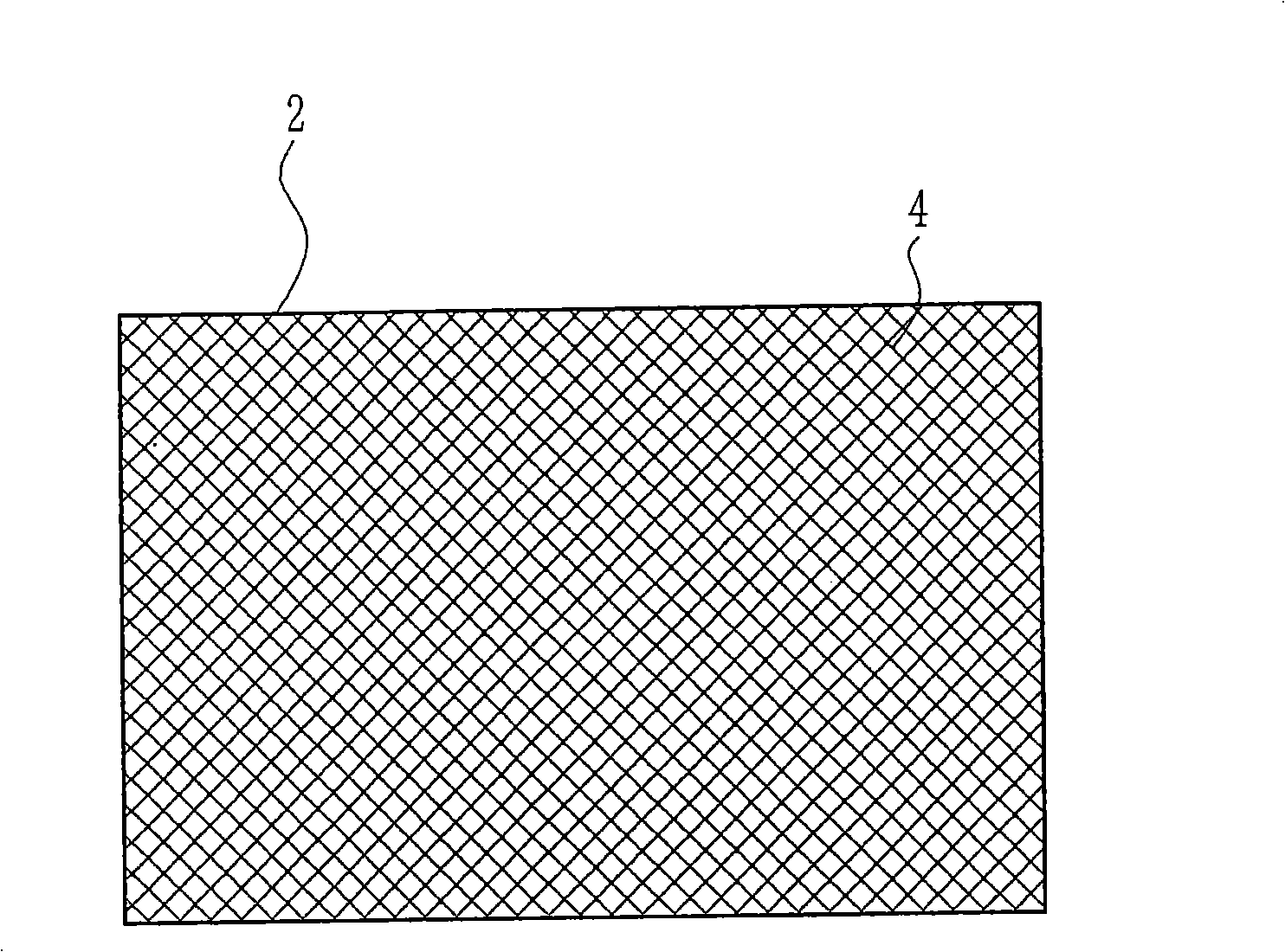
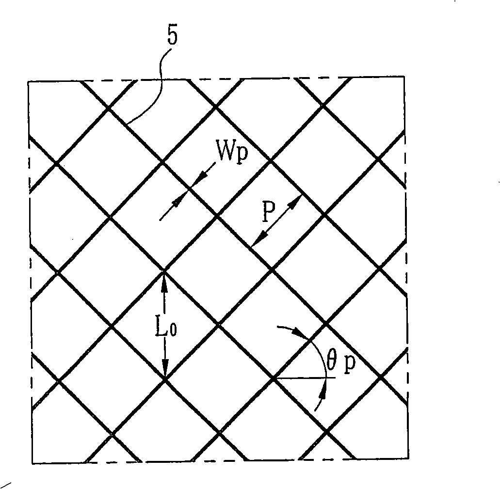
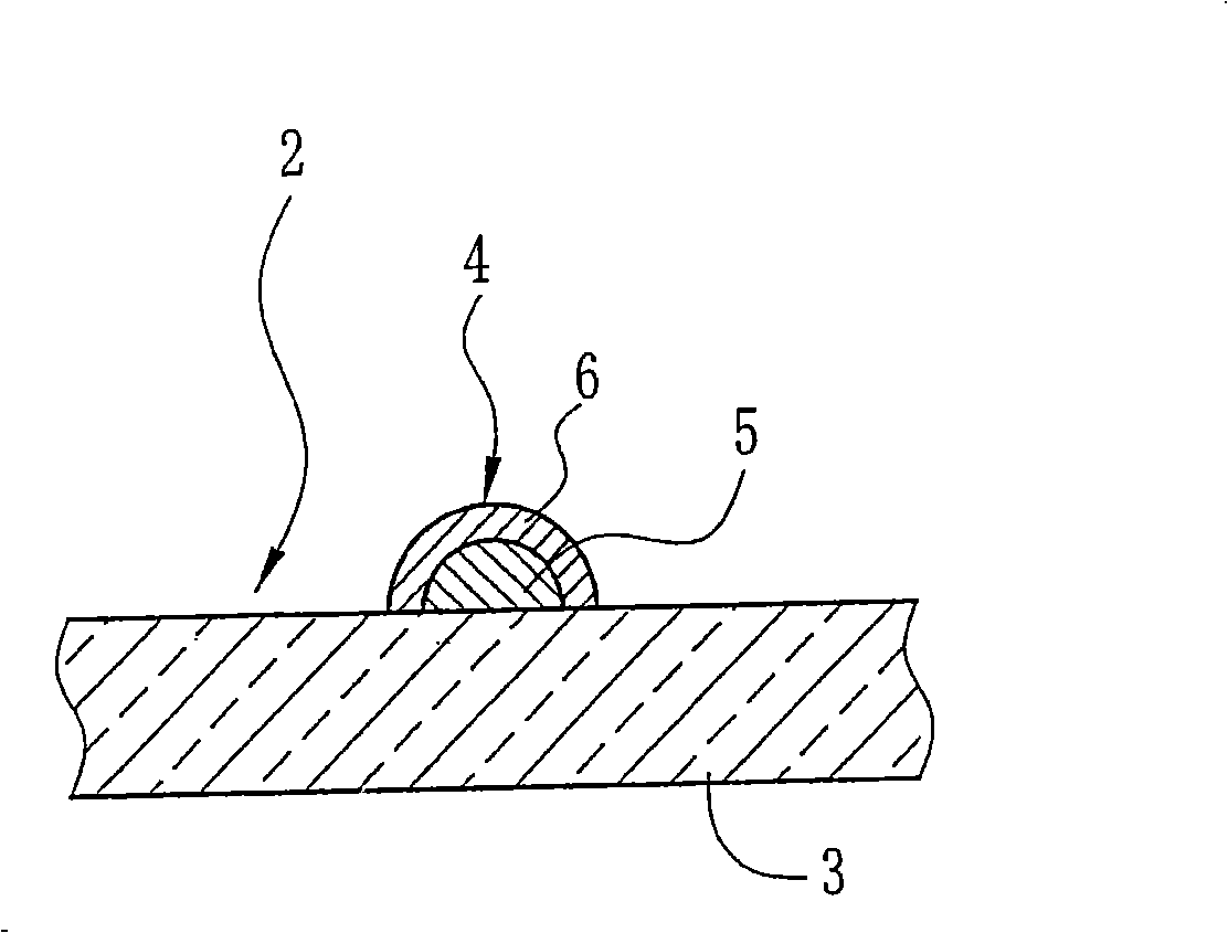
[0103] Such as Figure 1A As shown in , the electromagnetic shielding film 2 includes a transparent film 3 and a grid-like electromagnetic shielding pattern 4 of silver salt formed on the transparent film 3 . Such as figure 2 As shown in , the electromagnetic shielding pattern 4 is composed of a periodic pattern 5 formed of silver salt on a transparent film 3 and a copper plating layer 6 plated on the surface of the periodic pattern 5 for providing an electromagnetic shielding function. as in partially enlarged form Figure 1B As shown in , the periodic pattern 5 has thin lines arranged at right angles to each other at a pitch P of 300 μm and an alignment angle θp of 45°, each of which has a width Ws of 10 μm to 20 μm.

[0104] As shown in Figure 3, the pattern exposure apparatus 10 that is used to form periodic pattern 5 comprises: workpiece supply part 12, is used for supplying the tape-sample workpiece 11 as transparent f...


PUM

PropertyMeasurementUnit
Wavelengthaaaaaaaaaa
Line widthaaaaaaaaaa

Abstract

A belt-like work (11) provided with a photosensitive layer is conveyed in a work conveying direction F at a work conveying speed V. An illuminating section (30) illuminates a photomask (29) in an exposure period T synchronized with the work conveying speed V. The photomask (29) is disposed at a proximity gap from the belt-like work (11). Mask pattens (33) on the photomask (29) are exposed on the belt-like work (11) to form periodic pattens thereon.

Description

technical field [0001] The present invention relates to a pattern exposure method and equipment, in particular to a pattern exposure method and equipment for exposing a periodic pattern on a belt-like workpiece when it is conveyed. Background technique [0002] As an image display that is thin and has a large screen, a plasma display panel (hereinafter referred to as a PDP) in which light is generated by electric discharge between a front glass sheet and a rear glass sheet is widely used. In the PDP, in order to shield electromagnetic waves generated by discharge, an electromagnetic shield is provided. As for electromagnetic shielding, there is a thin metal film formed on the front glass sheet, and an electromagnetic shielding film disposed on the front side of the front glass sheet. Recently, electromagnetic shielding films having high shielding performance and high optical transparency are mainly used. The electromagnetic shielding film is a transparent film on which a m...

Claims


Application Information

Patent Timeline
IPC IPC(8): G03F7/20G02B26/12
Inventor 味野敏藤井武高田伦久
Owner FUJIFILM CORP
Why Eureka
Try Eureka