Clamping device for cylindrical face drilling of disk-shaped workpiece

A clamping device and cylindrical surface technology, which is applied to the drilling dies for workpieces and other directions, can solve the problems of difficult to locate the processing position, low processing efficiency, complicated clamping structure, etc. Easy to clip and disassemble, simple structure

Inactive Publication Date: 2018-05-25
ZHENGZHOU MOORE ELECTRONICS INFORMATION TECH CO LTD
View PDF11 Cites 3 Cited by
  • Summary
  • Abstract
  • Description
  • Claims
  • Application Information

AI Technical Summary

Problems solved by technology

[0002] The processing of disc-shaped parts has always been a difficult point in machining, especially for drilling the cylindrical surface of disc-shaped parts. The traditional clamping structure is very complicated, the assembly and disassembly are very troublesome, and the processing efficiency is relatively low. At the same time , it is difficult to find the processing position when drilling, resulting in relatively low processing accuracy

Method used


Image

  • Clamping device for cylindrical face drilling of disk-shaped workpiece
  • Clamping device for cylindrical face drilling of disk-shaped workpiece
  • Clamping device for cylindrical face drilling of disk-shaped workpiece

Examples


Embodiment Construction

[0016] The following will clearly and completely describe the technical solutions in the embodiments of the present invention with reference to the accompanying drawings in the embodiments of the present invention. Obviously, the described embodiments are only some, not all, embodiments of the present invention.

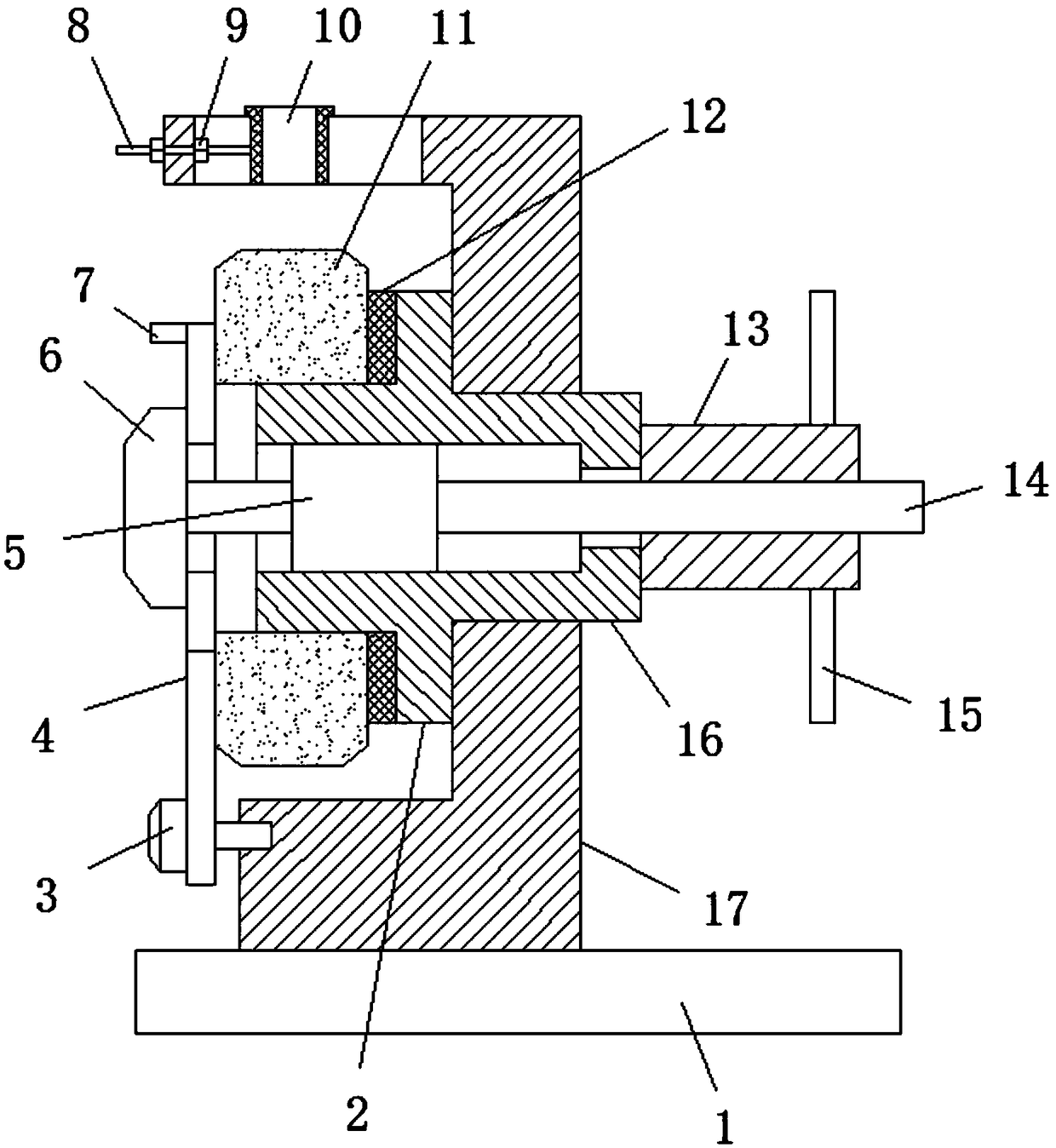
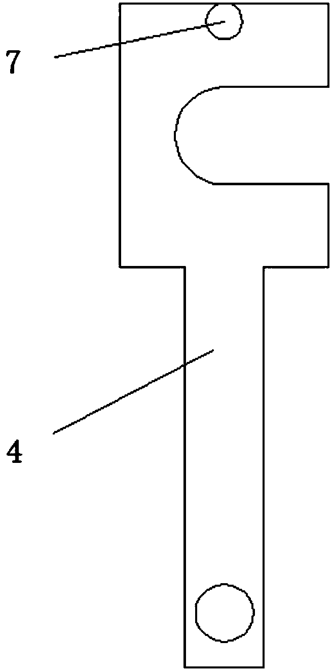
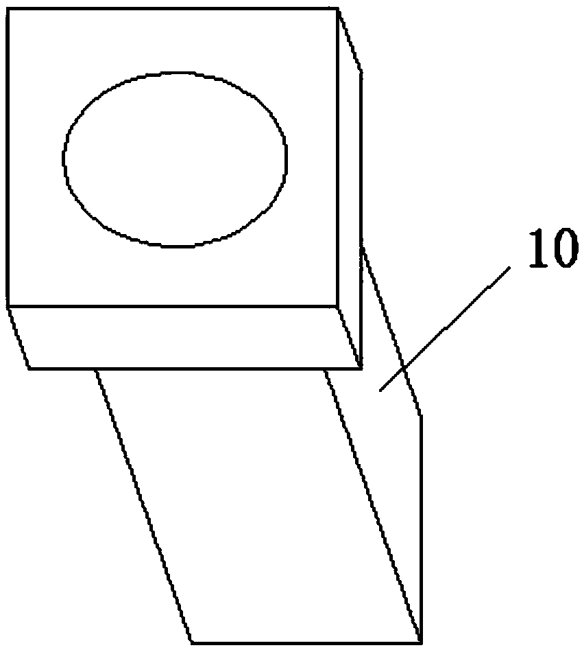
[0017] refer to Figure 1-4 , a clamping device for drilling a cylindrical surface of a disc-shaped workpiece, comprising a base 1, a C-shaped fixing seat 17 is installed on the top of the base 1, the side of the fixing seat 17 is fixedly inserted with a fixing sleeve 16, and the fixing sleeve 16 The outer fixed sleeve is connected with an annular limiting boss 2, and the inside of the fixed sleeve 16 is sleeved with a guide rod 14. One end of the rod 14 passes through the fixed sleeve 16 and is threadedly connected with the sleeve 13, the other end of the guide rod 14 passes through the fixed sleeve 16 and is fixed with the indenter 6, and the side of the sleeve 13 ...


PUM


Abstract

The invention discloses a clamping device for cylindrical face drilling of a disk-shaped workpiece. The clamping device for cylindrical face drilling of the disk-shaped workpiece comprises a base. Thetop of the base is provided with a C-shaped fixing base. A fixing sleeve is fixedly inserted to the side of the fixing base. The exterior of the fixing sleeve is fixedly sleeved with an annular limiting boss. A guide rod is sleeved with the fixing sleeve, the guide rod is fixedly sleeved with a sliding block, and the sliding block is in sliding connection with the inner wall of the fixing sleeve.One end of the guide rod penetrates out of the fixing sleeve and is sleeved with a sleeve through threads, and the other end of the guide rod penetrates out of the fixing sleeve and is fixedly provided with a pressing head. The side of the sleeve is provided with a rodlike first handle, the fixing sleeve is movably sleeved with a workpiece, a hinge pin is fixedly inserted to the side of the fixing base, the hinge pin is rotationally sleeved with an F-shaped pressing plate, the guide rod penetrates a notch in the pressing plate, and the pressing plate is located between the pressing head of the guide rod and the sliding block. By means of the clamping device for cylindrical face drilling of the disk-shaped workpiece, the mounting and demounting efficiency is improved, the workpiece clamping is very firm and reliable, the structure is simple, and very good practicality and novelty are achieved.

Description

technical field [0001] The invention relates to the technical field of fixtures, in particular to a clamping device for drilling a cylindrical surface of a disc-shaped workpiece. Background technique [0002] The processing of disc-shaped parts has always been a difficult point in machining, especially for drilling the cylindrical surface of disc-shaped parts. The traditional clamping structure is very complicated, the assembly and disassembly are very troublesome, and the processing efficiency is relatively low. At the same time , It is not easy to find the processing position when drilling, resulting in relatively low processing accuracy. Contents of the invention [0003] The purpose of the present invention is to solve the shortcomings in the prior art, and propose a clamping device for cylindrical surface drilling of disc-shaped workpieces. [0004] A clamping device for drilling a cylindrical surface of a disc-shaped workpiece, including a base, a C-shaped fixing se...

Claims


Application Information

Patent Timeline
Patent Type & Authority Applications(China)
IPC IPC(8): B23B47/28
CPCB23B47/28B23B2247/12
Inventor 邢济祥
Owner ZHENGZHOU MOORE ELECTRONICS INFORMATION TECH CO LTD
Why Eureka
Try Eureka