Large vehicle fuel tank with fuel-shaking alleviating function

A technology for fuel tanks and large vehicles, applied in power units, vehicle parts, transportation and packaging, etc., can solve the problems of unsmooth fuel supply, large cumulative impact of sub-oil chambers, and excessive fuel tank volume, and achieve smooth fueling. Effect

Inactive Publication Date: 2018-05-25
HUNAN UNIV OF ARTS & SCI
View PDF8 Cites 6 Cited by
  • Summary
  • Abstract
  • Description
  • Claims
  • Application Information

AI Technical Summary

Problems solved by technology

[0004] The partition arrangement in the first patent makes the height of each sub-oil chamber equal to the height of the overall oil chamber. Due to the large volume of the fuel tank of the dump truck, the volume of each sub-oil chamber is relatively large, and the cumulative impact of each sub-oil chamber is relatively large. Large, if the number of partitions is increased, too much fuel tank volume will be occupied, and this arrangement will easily cause unsmooth fuel supply due to the long length of the fuel tank when the car body encounters a large slope and less oil; In the second patent, the communication area between the sub-oil chambers is relatively large, and there is more liquid exchange during the shaking process. If the distance between the partition and the fuel tank wall is reduced, it will cause difficulties in the oil filling process.

Method used


Image

  • Large vehicle fuel tank with fuel-shaking alleviating function
  • Large vehicle fuel tank with fuel-shaking alleviating function
  • Large vehicle fuel tank with fuel-shaking alleviating function

Examples


Embodiment Construction

[0016] The present invention will be further described below in conjunction with the accompanying drawings.

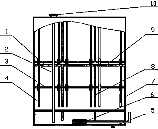
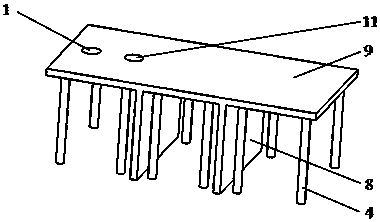
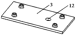
[0017] Such as figure 1 As shown, the structure of the fuel tank mainly includes: through hole 1, oil inlet pipe assembly 2, lightweight floating plate 3, guide column 4, oil discharge port 5, oil outlet pipe assembly 6, fuel tank shell 7, vertical partition Plate 8, horizontal partition 9, fuel tank cap 10. The upper end of the fuel inlet pipe assembly 2 is provided with an exhaust port, which is connected to the top of the fuel tank shell 7. The fuel tank cap 10 includes a pressure balance device; External connectivity. The horizontal partition 9 is welded on the fuel tank shell 7 in the horizontal direction, and divides the entire oil chamber into multiple vertically distributed secondary oil chambers, and only the horizontal partition between adjacent two secondary oil chambers The through hole 1 on the top is connected; the number of the horizontal partitions 9...


PUM


Abstract

The invention relates to a large vehicle fuel tank with a fuel-shaking alleviating function. The large vehicle fuel tank aims to reduce impact generated by fuel shaking to a fuel tank fixing structureand a vehicle body and reduce heat generated by fuel shaking in the operation process of a large vehicle. An inner cavity of the fuel tank is divided by horizontal partition plates into a plurality of vertically-distributed secondary oil cavities, and two through holes are formed in each horizontal partition plate, wherein one of the two through holes is used for arranging an oil inlet pipe, andthe other one of the two through holes is used for communicating the two corresponding adjacent secondary oil cavities. In the working process, saturated secondary oil cavities and non-oil secondary oil cavities cannot generate fuel impact, and therefore impact of fuel to the fuel tank is only limited to secondary oil cavities where the liquid levels are located. Longitudinal partition plates thendivide each secondary oil cavity into a plurality of horizontally-distributed third-level oil cavities communicating through seams, light floating plates are arranged in all third-level oil cavitiesexcept the bottommost oil cavities, and therefore impact of fuel in the fuel tank to the tank and the vehicle body is effectively lowered. Since the bottom secondary oil cavities are relatively small,oil supply is more sufficient and smoother to a dumper in a less-oil climbing state.

Description

technical field [0001] The invention relates to a large-scale vehicle fuel tank, in particular to a large-scale vehicle fuel tank with the function of alleviating oil sloshing. Background technique [0002] A vehicle's fuel tank is a container for storing fuel and is also the source of power for the engine. Large-scale engineering vehicles have a large workload, and their fuel consumption is very large, so the volume of the fuel tank also becomes large. Taking mining dump trucks as an example, for models with a load of more than 170t, it must have a large fuel tank of more than 2000L. At the same time, the working environment of general large-scale engineering vehicles is very harsh. When the oil in the fuel tank is in an unsaturated state, the oil inside the fuel tank is prone to sloshing, especially during turning and braking. And the fuel tank fixing device produces a great impact, which affects the driving stability of the vehicle and reduces the service life of the fu...

Claims


Application Information

Patent Timeline
Patent Type & Authority Applications(China)
IPC IPC(8): B60K15/077B60K15/03
CPCB60K15/03B60K15/077
Inventor 谷正气张沙陈旺林胡洪波
Owner HUNAN UNIV OF ARTS & SCI
Why Eureka
Try Eureka