Rotating shaft unit

A technology of rotating shaft device and rotating shaft, which is applied in the direction of pivot connection, etc., can solve problems such as unsmoothness, looseness, even yaw or tilt, and poor stability of the overall structure, so as to improve the strength of shear force and improve the structure The effect of strength and structural stability

Inactive Publication Date: 2018-05-25
HANWIT PRECISION IND LTD
View PDF3 Cites 0 Cited by
  • Summary
  • Abstract
  • Description
  • Claims
  • Application Information

AI Technical Summary

Problems solved by technology

[0004] However, the rotating shaft A is a unitary component and is passed through the through hole B1 of the first plate B and the through hole C1 of the second plate C. When the first plate B and the second plate C rotate relative to the axis A , it will cause the through hole B1 and the through hole C1 to easily have a large area of ​​contact and friction with the stop body A1 and the buckle end A2 of the rotating shaft A, resulting in the relative rotation of the first plate B and the second plate C. It is quite unsmooth due to a lot of resistance. If the first plate B or the second plate C is rotated with force, it will also cause burrs and debris to be easily generated on the rotating shaft A to form a jamming phenomenon. After excessive friction, a large gap will be formed, and then there will be looseness between the shaft A and the first plate B and the second plate C, and even yaw or tilting will occur, and the overall structural stability is also poor. It is difficult to meet the requirements of practicability, which is the direction for those who are engaged in this industry to study and improve.

Method used


Image

  • Rotating shaft unit
  • Rotating shaft unit
  • Rotating shaft unit

Examples


Embodiment Construction

[0029] In order to achieve the above-mentioned purpose and effect, the technical means and the structure thereof adopted in the present invention are hereby illustrated in detail with respect to the preferred embodiments of the present invention. Its features and functions are as follows, so as to fully understand.

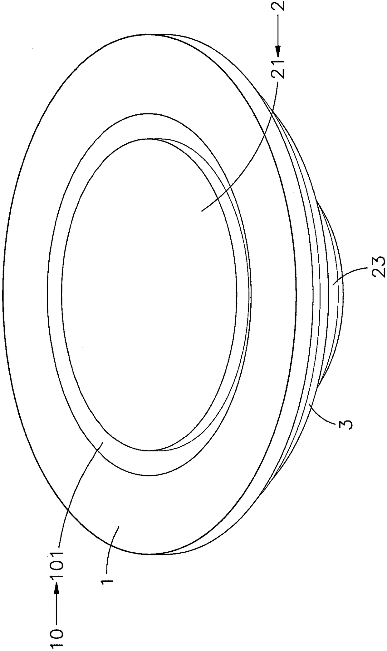
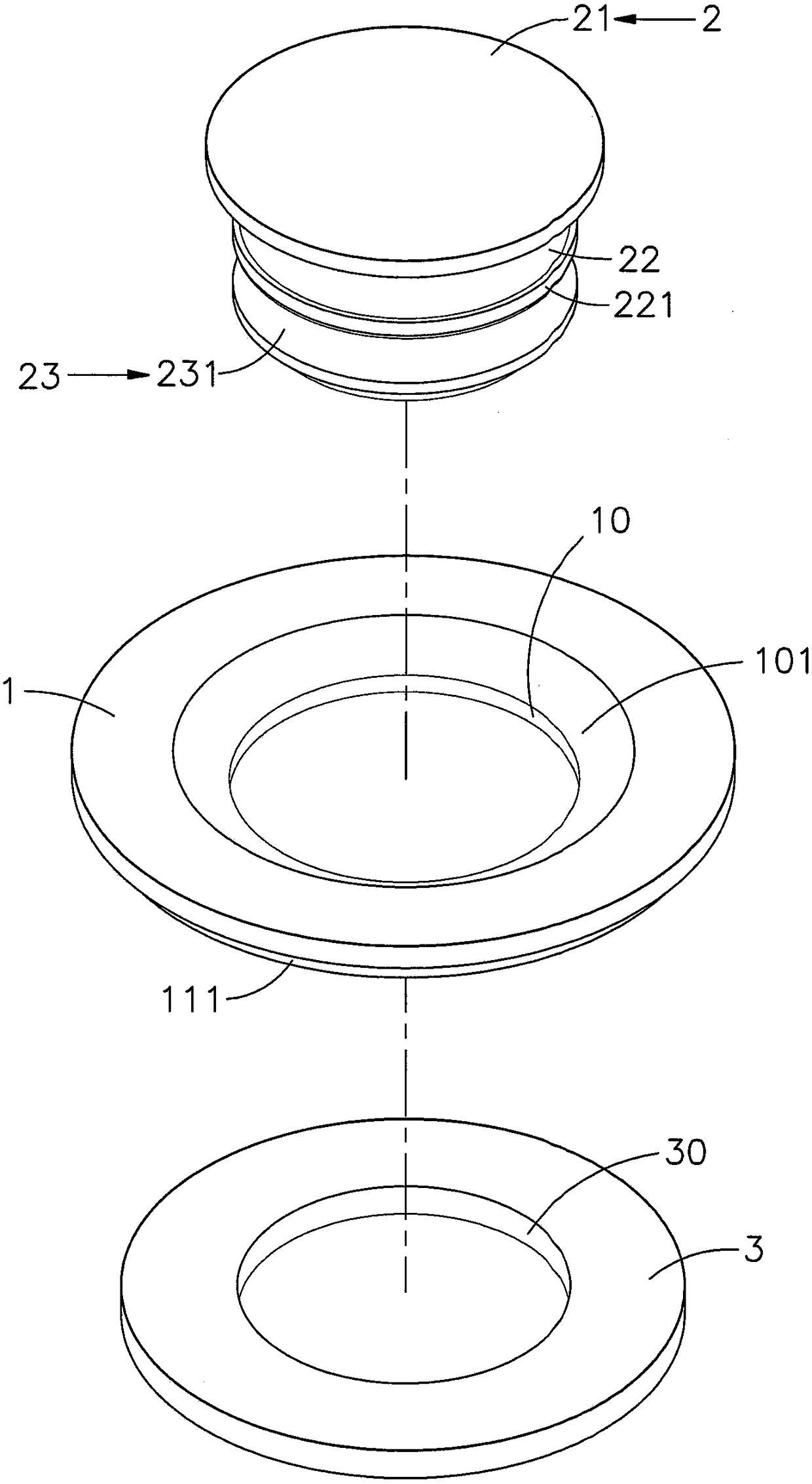
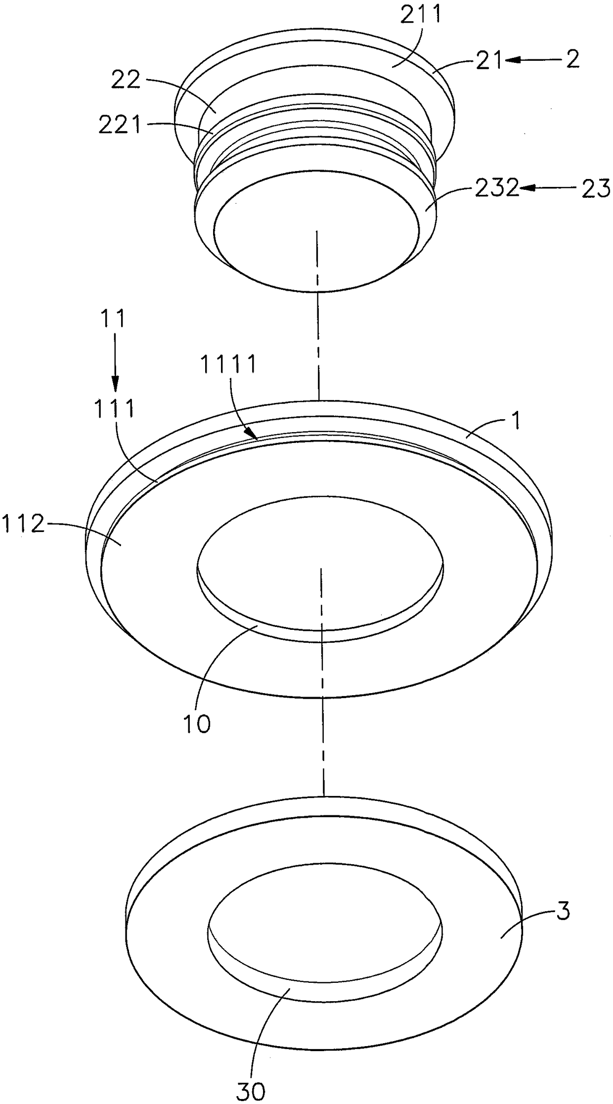
[0030] see figure 1 , figure 2 , image 3 , Figure 4 Shown are the three-dimensional appearance diagram, the three-dimensional exploded view, the three-dimensional exploded view of another angle of view and the side sectional view of the present invention. It can be clearly seen from the figure that the present invention includes a seat body 1, a rotating shaft 2 and a spacer 3 ,in:

[0031] The seat body 1 is integrally formed by a metal material (such as stainless steel, etc.) that cannot be deformed by stamping, and has the characteristics of high strength and high corrosion resistance. A stop surface 101 with a gradually expanding outer diameter is form...


PUM


Abstract

The invention provides a rotating shaft unit. The rotating shaft unit comprises a base, a rotating shaft and a pad, wherein the base does not deform under stamping; a rotating shaft capable of deformation under stamping is movably assembled into a shaft hole penetrating the base; the rotating shaft is provided with a head part pin-jointed in the shaft hole; a shaft column and a riveting part extending out of the shaft hole are arranged on the bottom surface of the head part; and the pad abutting against the bottom surface of the base is mounted on the shaft column. When the base is embedded ina first board in virtue of a butt joint part located at the outer side of the bottom, the riveting part can pass through a through hole in a second board, and the riveting part can be stamped throughstamping operation so as to allow the riveting part to deform and thus to abut against the inner wall surface of the through hole, so the first board and the second board can movably rotate relativeto each other in virtue of the base and the rotating shaft; and the pad is allowed to produce a damping frictional force during rotation, the rotation of the first board and the second board is allowed to be smoother and more stationary in virtue of the stamping riveting manner of the riveting part, and the thickness of the second board is reduced at the same time.

Description

technical field [0001] The invention relates to a rotating shaft device, especially a rotating shaft is installed in the shaft hole of the seat body, and a gasket is set on the shaft column of the rotating shaft. After the seat body is embedded in the first plate, the rotating shaft can be riveted by stamping The part is deformed and leans against the inner wall of the through hole of the second plate, and when the seat body and the rotating shaft rotate, the damping friction force generated by the gasket can be used to achieve the effect of making the rotation stable. Background technique [0002] Press, the general shaft system provides mutual connection between two components, and enables one of the components to rotate relative to the other to have the function of rotation, and many products will use the shaft structure, such as doors, windows, and telecom cabinets. , industrial computer, work machine, etc., the shaft can be used as a door panel, window panel, frame pane...

Claims


Application Information

Patent Timeline
Patent Type & Authority Applications(China)
IPC IPC(8): F16C11/04
CPCF16C11/04
Inventor 吴明德陈智远
Owner HANWIT PRECISION IND LTD
Why Eureka
Try Eureka