
Clamping device of probe unit used for display panel detection

A probe unit and display panel technology, applied to static indicators, instruments, etc., can solve problems such as the shrinkage of the probe unit 2, the decrease in the accuracy of the flatness of the probe card, and the poor arrangement of the probe unit 2. And the effect that it is easy to replace and the arrangement state is excellent

Inactive Publication Date: 2018-05-25
YOUNG WOO DSP
View PDF5 Cites 0 Cited by
  • Summary
  • Abstract
  • Description
  • Claims
  • Application Information

AI Technical Summary

Problems solved by technology

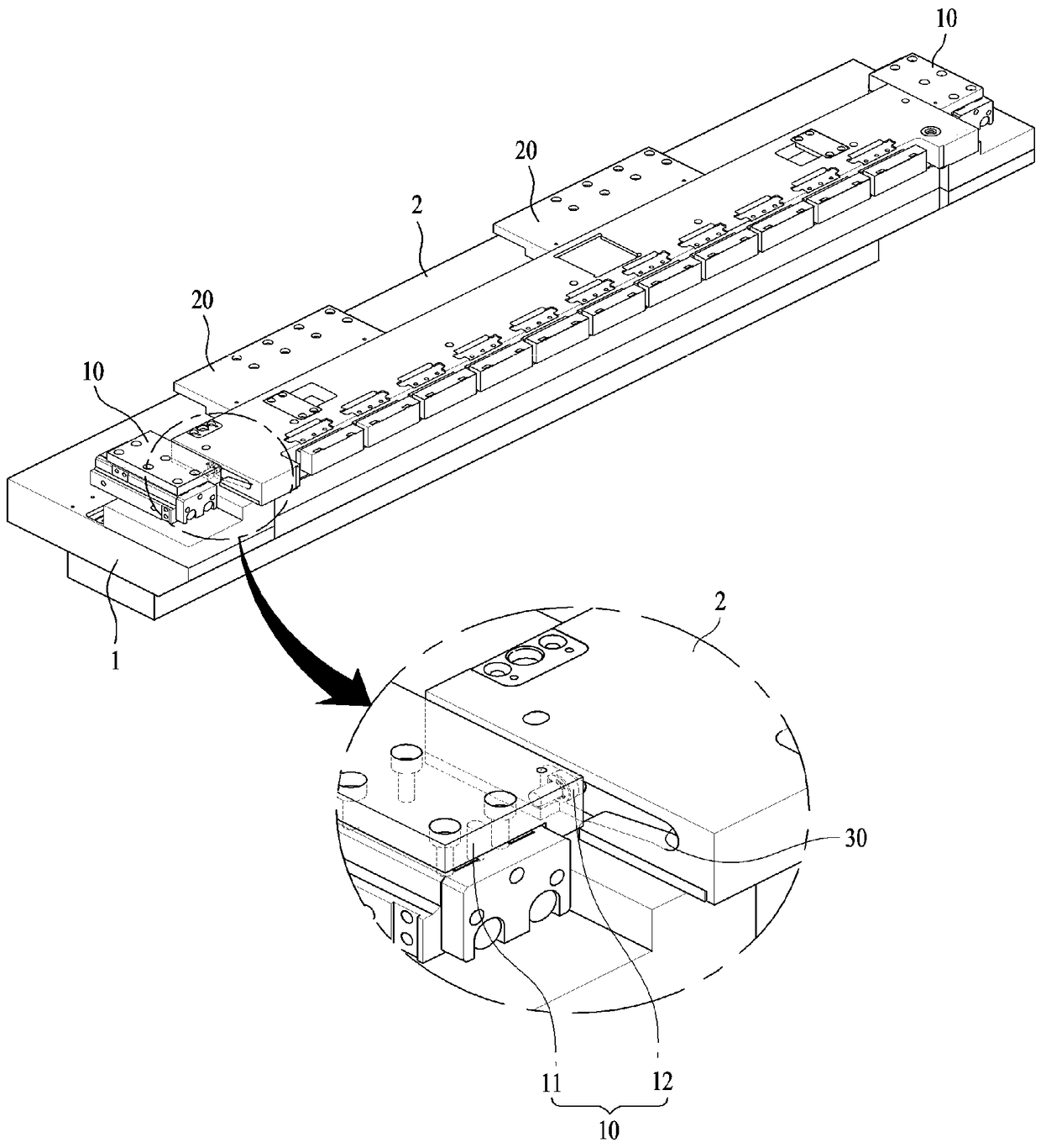
[0010] However, the conventional probe unit clamping device for display panel detection adopts a method in which a plurality of cams 10, 20 move to one side and form a clamping mode at the same time. During the clamping process, the probe unit 2 is laterally clamped. Continuous application of external force in the tight direction causes poor alignment of the probe unit 2
In addition, the longer the length of the probe unit 2, the more clamping devices are installed, and the degree of poor alignment of the probe unit 2 will also increase.
[0011] As mentioned above, the traditional probe unit clamping device for display panel inspection is that the replacement of the probe unit 2 is easy and convenient to a certain extent, but in the clamping process, the arrangement state of the probe unit 2 will change. Poor, which leads to a serious problem that the accuracy of the flatness of the probe card decreases
[0012] On the other hand, when testing with a conventional probe unit clamping device for inspection of display panels, the probe unit 2 may shrink slightly in the longitudinal direction due to the internal environment of the testing chamber.
[0013] That is to say, for OLED display panels, in terms of the characteristics of the screen, in order to avoid oxidation of the screen during the detection process, the detection is carried out in an inert gas environment, but the temperature of the inert gas is lower than normal temperature, so the probe unit 2 is moved to the detection room There will be slight shrinkage during the internal process
[0014] The shrinkage of the probe unit 2 mainly occurs along the length direction of the probe unit 2. As a result, the cam roller 12 cannot be smoothly inserted into the clamping groove 30, and further cannot be clamped normally. Multiple probes formed at fine pitches cannot normally contact each electrode sheet, which greatly reduces the reliability of detection

Method used


Image

  • Clamping device of probe unit used for display panel detection
  • Clamping device of probe unit used for display panel detection
  • Clamping device of probe unit used for display panel detection

Examples


Embodiment Construction

[0047] In order to make the features, technical solutions and advantages of the present invention clearer, the preferred embodiments of the present invention will be clearly and completely described below in conjunction with the accompanying drawings in the embodiments of the present invention. The terms or words used in the specification and claims are, in principle, properly defined by the inventors in order to describe their own invention in the best way, and therefore should be interpreted with meanings and concepts consistent with the technical solution of the present invention.

[0048] An embodiment of the present invention will be described in detail below in conjunction with the accompanying drawings. The same symbols are used for the same structure, and the same parts will not be repeated in the description, and the different parts will be explained emphatically for a clearer description.

[0049] Such as Figure 2 to Figure 4 As shown, the present invention is appli...


PUM


Abstract

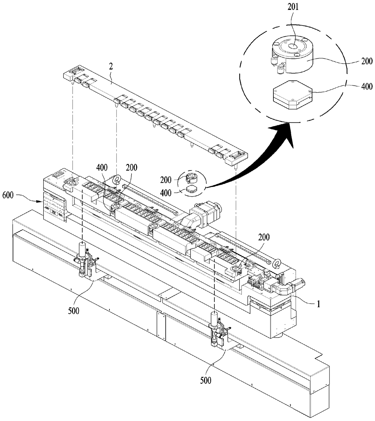
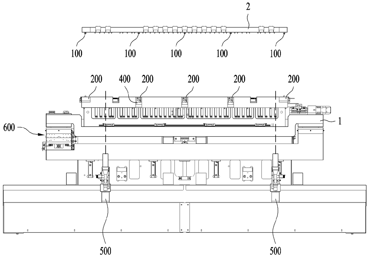
The invention relates to a clamping device of a probe unit used for display panel detection. The probe unit is precisely and firmly fixed on a pedestal for display panel detection, so that a probe clamp assembled to the probe unit forms precise flatness. The clamping device of the probe unit used for display panel detection includes: the bottom surface of the probe unit is provided with more thanone fixed pin and the fixed pins are formed by protruding from the pedestal, the upper portion of the pedestal is provided with ball clamps that correspond to the fixed pins and fix the fixed pins oneby one, and more than one of the ball clamps can be configured by moving in the length direction of the probe unit through a transfer device arranged on the upper portion of the pedestal. The probe unit assembled with the probe clamp can be fixed to the pedestal for display panel detection and can also be clamped by the pedestal successfully when contracting, and detection credibility will not bereduced.

Description

technical field [0001] The present invention relates to a probe for detecting whether a display panel is defective or not. Specifically, in order to form a precise flatness of a probe card assembled on a probe for display panel inspection, the probe unit supporting the probe card is precisely and firmly fixed on the Clamping device for the probe unit for display panel inspection on the base for display panel inspection. Background technique [0002] The display panels used for TVs, notebook computers or mobile phones are generally provided with a plurality of electrode sheets at fine pitches, which are used to apply various electrical signals such as image signals, synchronous signals, and color signals to the edges. [0003] After the display panel is manufactured, probes are used to apply electrical signals to the electrode sheets, so as to detect whether pixels are defective. [0004] The composition of the conventional probe for display panel inspection includes: a prob...

Claims


Application Information

Patent Timeline
Patent Type & Authority Applications(China)
IPC IPC(8): G09G3/00
CPCG09G3/006
Inventor 曹范尚金铉谦李昌烈
Owner YOUNG WOO DSP
Learn More