Milling cutter being convenient to use
A milling cutter and convenient technology, applied in the field of milling cutters and cutting tools, can solve the problems of affecting the use effect and the cutting effect of debris liquid, and achieve the effect of good cutting effect and avoiding the effect of the impact.
- Summary
- Abstract
- Description
- Claims
- Application Information
AI Technical Summary
Problems solved by technology
Method used
Image

Examples
Embodiment Construction
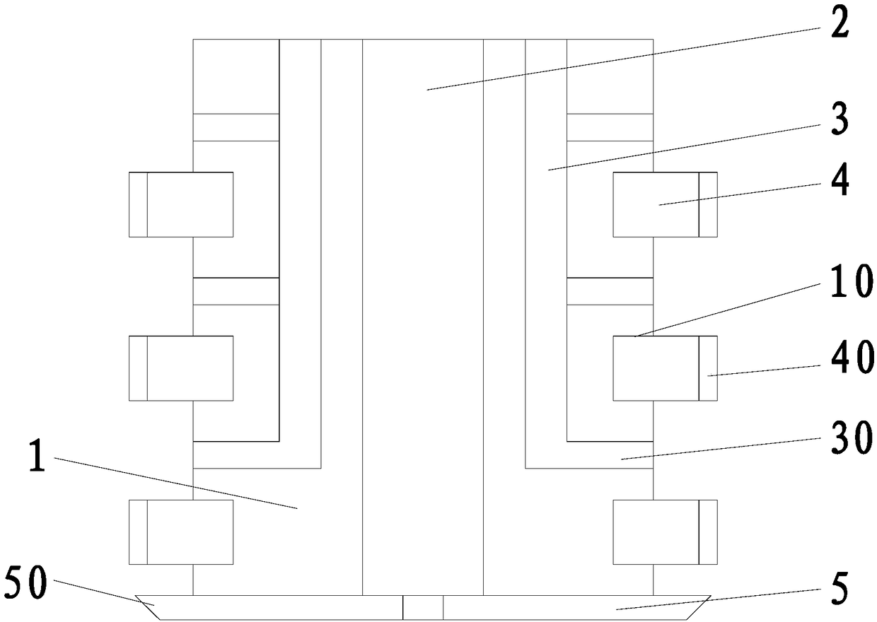
[0015] refer to figure 1 , an easy-to-use milling cutter of the present invention, comprising a main rod body 1, a fixing groove 10, a fixing block 4, a side wall milling edge 40, a bottom milling edge 5, a side milling edge, an air suction hole 2, and a liquid spray hole 30. The main rod is cylindrical, and the outer wall of the main rod body 1 is provided with a number of fixing grooves 10. The fixing grooves 10 are equipped with detachable fixing blocks 4, and the fixing blocks 4 are provided with side wall milling cutter blades 40. The bottom of the main rod body 1 is fixed with a number of detachable bottom milling cutter blades 5, the main rod body 1 is provided with an air suction hole 2 that runs through the upper and lower ends of the main rod body 1, and the main rod body 1 is provided with a ring-shaped nozzle The liquid tank 3 and the outer wall of the liquid spray tank 3 are provided with a number of liquid spray holes 30, the water outlet ends of the liquid spray...
PUM
 Abstract
Description
Claims
Application Information
 - Generate Ideas
- Intellectual Property
- Life Sciences
- Materials
- Tech Scout
- Unparalleled Data Quality
- Higher Quality Content
- 60% Fewer Hallucinations
Browse by: Latest US Patents, China's latest patents, Technical Efficacy Thesaurus, Application Domain, Technology Topic, Popular Technical Reports.
© 2025 PatSnap. All rights reserved.Legal|Privacy policy|Modern Slavery Act Transparency Statement|Sitemap|About US| Contact US: help@patsnap.com