Finish grinding machining method for inner cavity of middle cylinder
A technology of precision grinding and inner cavity, which is applied in the direction of grinding workpiece supports, metal processing equipment, machine tools designed for grinding workpiece rotating surfaces, etc. Avoid the effect of shaking from side to side
- Summary
- Abstract
- Description
- Claims
- Application Information
AI Technical Summary
Problems solved by technology
Method used
Image
Examples
Embodiment 1
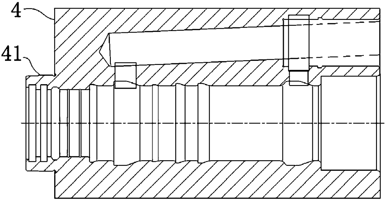
[0044] Combine figure 1 , It is the conventional structure of the large-sized middle cylinder body 4, because its main structure is rectangular, it is easy to swing when rotating. More importantly, during the fine grinding process, it is necessary to insert the tool from one side of the middle cylinder body 4, so it can only be fixed from one end; however, due to the heavy weight of the middle cylinder body 4, deformation cannot be avoided, resulting in grinding The amount is not easy to control.
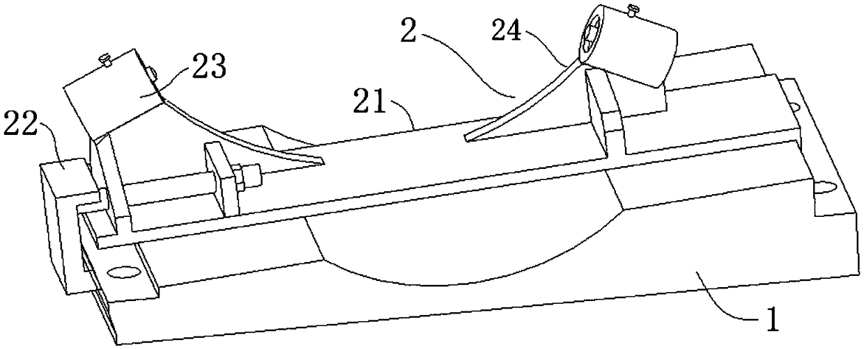
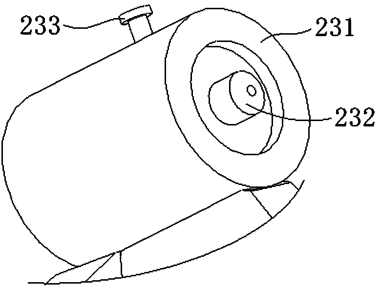
[0045] In this embodiment, a precision grinding support device for the inner cavity of the middle cylinder can be used to support the middle cylinder 4 from the other end, that is, the cylinder journal 41 can be lifted to improve the machining accuracy. Specifically, combine figure 2 with Figure 8 The device includes a base 1, a supporting table 2 and a disc 3. The base 1 is provided with a mounting screw hole 17, and a bolt is inserted into the mounting screw hole 17, and the base ...
Embodiment 2
[0055] The basic structure of a fine grinding support device for the inner cavity of the middle cylinder of this embodiment is the same as that of embodiment 1, and further: Figure 7 As shown, the support stand 21 in this embodiment is mainly composed of a first seat plate 211 and a second seat plate 212. The first seat plate 211 constitutes the base plate of the support stand 21. The second seat plate 212 is equivalent to a stopper. The seat plate 212 is located at the end of the first seat plate 211 and forms the bayonet with the first seat plate 211. The included angle of the bayonet is α; the vertical section of the first step opening 11 and the upper surface of the base 1 are also clamped Is α, the range of the included angle α is 78-85°, and 82° is adopted in this embodiment. Since the two angles are the same, they can cooperate with each other.
[0056] If the included angle α is too small, the inclination angle of the upper surface of the base 1 is too large, the vertica...
Embodiment 3
[0058] The basic structure of the inner cavity fine grinding support device of the middle cylinder of this embodiment is the same as that of Embodiment 2. Furthermore: the spine plate 24 in this embodiment is mainly composed of a longitudinal spine plate 241 and a transverse spine plate 242, The longitudinal spine plate 241 and the transverse spine plate 242 are perpendicular to each other, and the inner side of the longitudinal spine plate 241 is set in an arc shape to avoid interference with the disk 3.
[0059] A bolt pull plate 25 is also fixed on the support base 21. The bolt pull plate 25 is parallel to the transverse spine plate 242. The transverse spine plate 242 and the bolt pull plate 25 have bolt holes perpendicular to each other, that is, bolts are arranged along the length of the support base 21. A fastening bolt 26 is installed in the bolt hole. The outer end of the fastening bolt 26 is connected to the fastening chuck 22. The lower end of the fastening chuck 22 can ...
PUM
 Abstract
Description
Claims
Application Information
 - R&D
- Intellectual Property
- Life Sciences
- Materials
- Tech Scout
- Unparalleled Data Quality
- Higher Quality Content
- 60% Fewer Hallucinations
Browse by: Latest US Patents, China's latest patents, Technical Efficacy Thesaurus, Application Domain, Technology Topic, Popular Technical Reports.
© 2025 PatSnap. All rights reserved.Legal|Privacy policy|Modern Slavery Act Transparency Statement|Sitemap|About US| Contact US: help@patsnap.com


