Inkstone grinder

An ink-stone and ink-grinding technology, applied in ink-table, printing, office supplies, etc., can solve the problems of waste, difficulty, and inability to reuse ink sticks, and achieve adjustable ink grinding pressure and speed, controllable ink concentration, Avoid wasteful effects

Pending Publication Date: 2018-05-29
米姿颖
View PDF11 Cites 3 Cited by
  • Summary
  • Abstract
  • Description
  • Claims
  • Application Information

AI Technical Summary

Problems solved by technology

It is difficult to grind ink with artificial inkstones to meet the above requirements, especially for beginners of calligraphy and painting, it is difficult to master the strength of grinding ink, the speed of grinding ink and the concentration of ink
[0005] Since Yao Mengqi invented the ink grinding machine in 1879, there have been many kinds of ink grinding machines at home and abroad. The types can be summarized into three types. One is the grinding disc type, the ink block does not move and the inkstone rotates; the other is imitating the manual inkstone grinding ink. type, the ink stick turns and the inkstone does not move; the third is the cross type, both move, the ink stick shakes back and forth, and the inkstone turns; they all have the following disadvantages: one is that the ink stick is used for

Method used


Image

  • Inkstone grinder
  • Inkstone grinder
  • Inkstone grinder

Examples


Embodiment 1

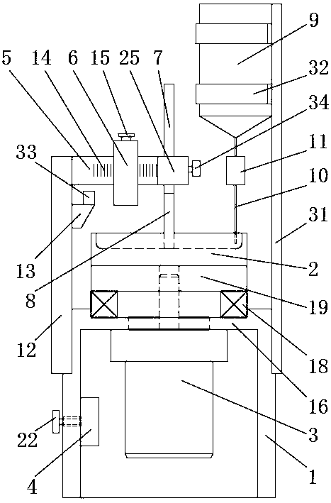
[0038] Such as figure 1 , 2, 4, 5, 6, and 8, the inkstone grinder includes an underframe 1 and an inkstone 2, a frequency modulation motor 3 and a frequency modulation controller 4 are fixedly installed in the underframe 1, and the frequency modulation controller 4 is connected with the frequency modulation motor 3 and The speed of the frequency modulation motor 3 can be adjusted. Specifically, the frequency modulation controller 4 is connected to the frequency modulation motor 3, and can control the frequency modulation motor 3 to change its operating frequency, thereby realizing the adjustment of the speed of the frequency modulation motor 3. The frequency modulation controller 4 is installed on the chassis 1 On the inner wall of the middle part, an adjustment indicator panel 21 is installed on the outer wall of the middle part of the chassis 1. The adjustment indicator panel 21 has an AC frequency adjustment indicator bar (not shown in the figure), and the adjustment rod 23...

Embodiment 2

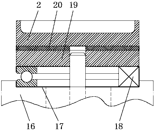
[0045] Such as figure 1 , 3 , 4, on the basis of embodiment 1, a top plate 16 is provided at the top of the underframe 1, and a through hole is provided on the top plate 16. A plane bearing 18 is fixedly installed in the groove 17. Specifically, the lower ring of the plane bearing 18 is fixedly installed in the installation groove 17. The upper ring does not contact the installation groove 17 and can rotate relative to the lower ring. The upper end surface of the plane bearing 18 is fixed. A horizontal grinding disc 19 is installed, and the grinding disc 19 is fixedly connected with the upper ring. The output shaft of the frequency modulation motor 3 passes through the through hole and the plane bearing 18 and is fixedly connected with the grinding disc 19. The inkstone 2 is arranged on the grinding disc 19. The frequency modulation motor 3 It can control the rotation of the grinding disc 19 relative to the base frame 1, and then control the rotation of the inkstone 2. This a...

Embodiment 3

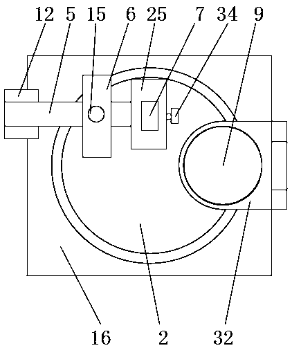
[0048] Such as figure 1 , 2 , 7, 9 to 11, on the basis of embodiment 2, the ink stick assembly is detachably fixed and installed on the end of the crossbeam 5 through the chuck mechanism, and the end of the crossbeam 5 is provided with a threaded hole 24, specifically here Three threaded holes 24 are provided, and the chuck mechanism includes a chuck body 25, and a vertical ink stick assembly mounting hole 26 is provided on the chuck body 25, and the ink stick assembly can be suitably installed in the ink stick assembly mounting hole 26 Inside, the chuck body 25 is provided with a stepped hole 27 on the left side of the ink stick assembly mounting hole 26. The stepped hole 27 corresponds to the threaded hole 1 24, and three stepped holes 27 are correspondingly opened. 28 passes through the stepped hole and screws into the corresponding threaded hole 24 to realize the fixed connection between the chuck body 25 and the crossbeam 5. The stepped hole 27 can make the head of the f...


PUM


Abstract

The invention relates to the technical field of ink grinding, and discloses an inkstone grinder. The inkstone grinder comprises an underframe and an inkstone, wherein a frequency modulation motor anda frequency modulation controller are fixedly connected to the underframe, and the speed of the frequency modulation motor can be adjusted by the frequency modulation controller; an output shaft of the frequency modulation motor protrudes from the top of the underframe, and the top end of the output shaft is connected with the inkstone and is capable of controlling the inkstone to rotate; a crossbeam is arranged on the upper end of the underframe, the cross beam can rotate relative to the underframe in a vertical plane, a weight is arranged on the cross beam and can move in the length direction, an ink block assembly is installed on the end of the cross beam, the ink block assembly comprises an extension rod and an ink block, the upper end surface of the ink block makes contact with and is fixedly connected with the lower end surface of the extension rod, the ink block assembly is perpendicular to the cross beam and can be adjusted up and down relative to the cross beam, and the lowerend of the ink block makes contact with the grinding surface of the inkstone; and a water pot is arranged on the upper end of the underframe, a hose is connected to the bottom of the water pot, a drip control valve is arranged on the hose, and the bottom end of the hose is aligned with the grinding surface of the inkstone. The ink block can be effectively used, the waste is avoided, the ink grinding pressure and speed can be adjusted, and the ink concentration can be controlled.

Description

technical field [0001] The invention relates to the technical field of ink grinding, in particular to an inkstone grinding device. Background technique [0002] At present, the ink glue pens sold in the market are heavy and stagnant. After adding water, the ink will not turn black and the paper will melt. In order to prevent sedimentation and corruption, electrolytes and preservatives are added to the ink. . [0003] Inkstones have less glue for grinding ink, and the brushwork is smooth. The books and paintings made with grinding ink are more beautiful in color and have a sense of hierarchy. The grinding ink is more adaptable to paper and can be used at any time. Obviously grinding ink is better. . [0004] When grinding ink on the inkstone, the strength of the ink block on the inkstone should be appropriate, the fluctuation should be small, and the speed should be moderate. If the force is too fast, the ink will be thick and uneven. If the ink is too fast, the ink will b...

Claims


Application Information

Patent Timeline
IPC IPC(8): B43L27/00
CPCB43L27/00
Inventor 米姿颖
Owner 米姿颖
Why Eureka
Try Eureka