Headlamp control device

A technology for control devices and headlights, applied in signal devices, vehicle components, transportation and packaging, etc., can solve the problems of blind spots, low angles of irradiation, and short irradiation distances, and achieve the effects of saving material costs and avoiding irradiation

Active Publication Date: 2018-05-29
上海晨阑光电器件有限公司
View PDF8 Cites 8 Cited by
  • Summary
  • Abstract
  • Description
  • Claims
  • Application Information

AI Technical Summary

Problems solved by technology

[0002] At present, the headlights of automobiles are divided into high beam + low beam. The high beam is for the driver to better recognize the road conditions ahead of the vehicle on the expressway, but its illumination also seriously affects the sight of the opposite driver, which is likely to cause traffic accidents.
Not only that, but in the state of following the car, it will also dazzle the vehicle in front and affect driving safety
Although the current car headlights are illuminated in the way of low beam + high beam, in order to avoid dazzling the driver caused by illuminating the vehicle in front, usually the angle of illumination of the low beam is low, and the driver switches to the low beam when there is a vehicle coming from the opposite side. Low beam, although the low beam will not affect the driver of the other vehicle, but due to the low irradiation angle, it has the defects of short irradiation distance and narrow irradiation width, which affects the irradiation effect to a certain extent
And in fact, many drivers will not 100% consciously and actively switch to low beam when meeting cars, which has a great impact on the safe driving of vehicles
Ordinary low beam irradiation width is not enough. On some rural roads with poor lighting, there will be blind spots when the vehicle turns, and the vehicle is easy to bump into other objects or pedestrians when turning

Method used


Image

  • Headlamp control device
  • Headlamp control device
  • Headlamp control device

Examples


Embodiment 1

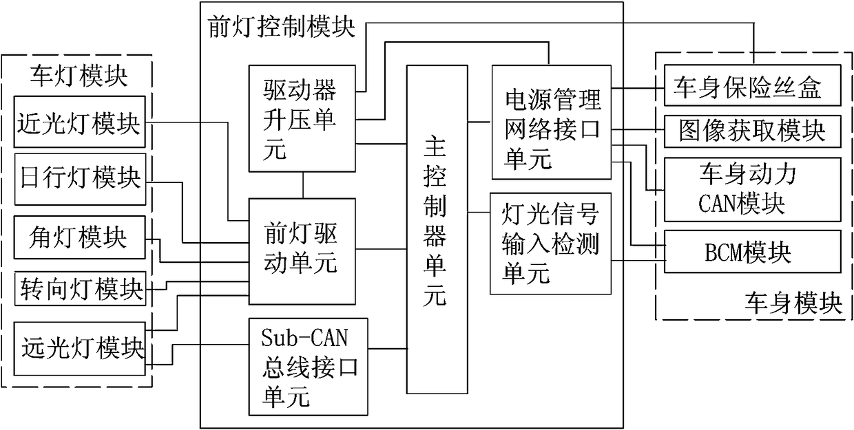
[0035] according to figure 1 The present invention is a headlight control device, comprising a headlight module, a headlight control module and a body module which are connected in sequence.

[0036] The vehicle lamp module includes a low beam lamp module, a high beam lamp module, a corner lamp module, a turn signal module, and a daytime running lamp module.

[0037] The body module includes an image acquisition module, a body power CAN module, a body fuse box, and a BCM module. The image acquisition module may use a camera module, wherein the body fuse box and the BCM module are inherent modules common to automobiles. The image acquisition module described in this embodiment adopts a camera.

[0038] The headlight control module includes a main controller unit, a power management network interface unit, a driver boosting unit, a headlight driving unit, and a Sub-CAN bus interface unit respectively connected to the main controller unit.

[0039] The high beam module includes...

Embodiment 2

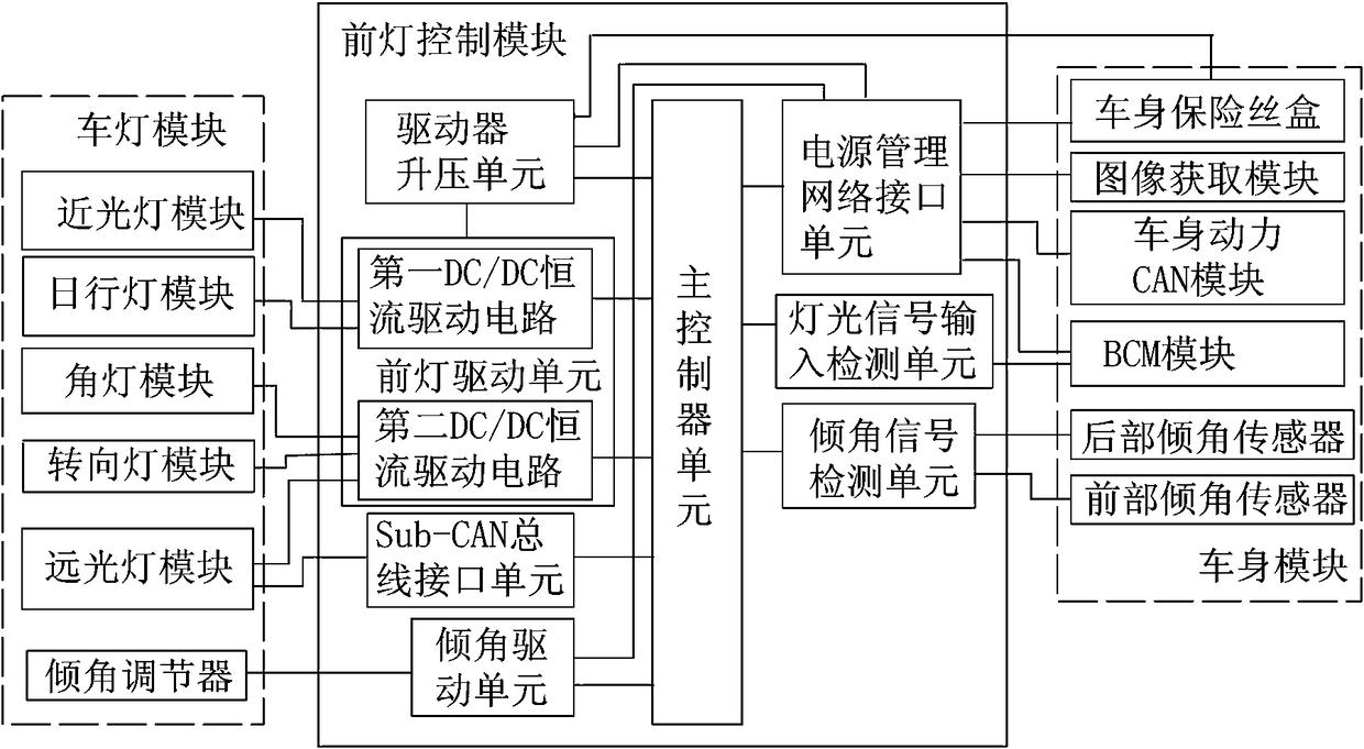
[0062] according to figure 2 In addition to the above modules, this embodiment also includes the following modules: the headlight control module further includes an inclination signal detection unit and an inclination driving unit respectively connected to the main controller unit, and the body module further includes a front inclination sensor and a rear inclination sensor connected to the inclination signal detection unit; the vehicle lamp module further includes an inclination adjuster connected with the inclination driving unit; the inclination signal detection unit receives the front inclination sensor and the rear inclination sensor; The PWM duty cycle signal of the partial inclination sensor is sent to the main controller unit; the main controller unit controls the inclination drive unit to drive the inclination adjuster through the PWM duty cycle signal to adjust the low beam The illumination angle of the module, main beam module or corner light module. The tilt driv...

Embodiment 3

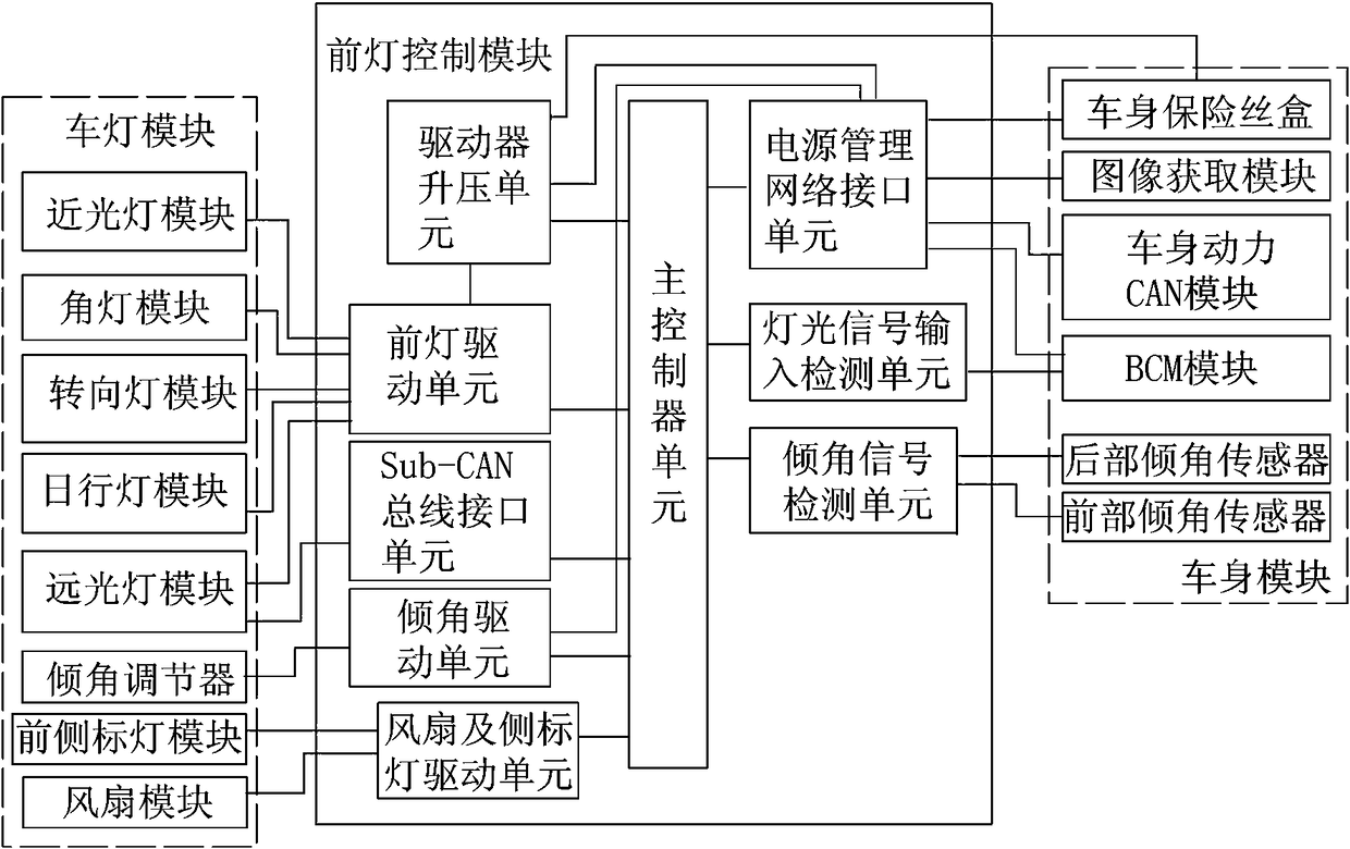
[0065] according to image 3 In addition to all the modules of the second embodiment, this embodiment also includes the following modules: the vehicle lamp module further includes a front side marker lamp module and a fan module; the headlamp control module further includes a fan and a side marker lamp drive unit; The front side marker lamp module and the fan module are respectively connected with the fan and the side marker lamp driving unit.


PUM


Abstract

The invention relates to a headlamp control device. The headlamp control device comprises an automobile lamp module, a headlamp control module and an automobile body module which are sequentially connected and is characterized in that the automobile lamp module comprises a low-beam headlamp module and a high-beam headlamp module; the automobile body module comprises an image acquiring module and an automobile body power CAN module; the headlamp control module comprises a main controller unit and a driver boosting unit, a headlamp drive unit and a Sub-CAN bus interface unit which are connectedwith the main controller unit. The headlamp control module has the advantages that the high-beam headlamp module is divided into a plurality of regional lamp groups, the image acquiring module of theautomobile body module identifies road conditions and vehicle information in front of a corresponding automobile, the road conditions and vehicle information are transmitted to the headlamp control module, the automobile body power CAN module transmits the traveling information of the corresponding automobile to the headlamp control module, and the headlamp control module controls the brightness of the regional lamp groups according to the road conditions and vehicle information and the traveling information.

Description

technical field [0001] The invention relates to a vehicle lamp, and particularly discloses a headlamp control device. Background technique [0002] At present, the headlights of automobiles are divided into high beam and low beam. The high beam is for the driver to better identify the road conditions in front of the vehicle on the highway, but its illumination also seriously affects the sight of the driver on the opposite side, which can easily cause traffic accidents. Not only that, in the state of following the car, it will also cause dazzling to the vehicle ahead, affecting the driving safety. Although the current car headlights are illuminated in the way of low beam + high beam, in order to avoid dazzling the driver by illuminating the vehicle in front, the illumination angle of the low beam is usually low, and the driver switches when there is a vehicle on the opposite side. The low beam and low beam will not affect the driver of the other vehicle, but due to the low i...

Claims


Application Information

Patent Timeline
Patent Type & Authority Applications(China)
IPC IPC(8): B60Q1/076B60Q1/08B60Q1/14B60R16/023
CPCB60Q1/076B60Q1/08B60Q1/14B60R16/023Y02B20/40
Inventor 钱建斌
Owner 上海晨阑光电器件有限公司
Why Eureka
Try Eureka