Assembled shear wall formed by combining square steel pipes with steel plate concrete

A steel plate concrete and combined shear wall technology, applied in walls, building components, buildings, etc., can solve the problems of weak joint strength, poor seismic performance, early cracks, etc., to achieve reliable seismic performance guarantee, improve lateral ability, Definite force effect

Active Publication Date: 2018-05-29
CHINA CONSTR STEEL STRUCTURE CORP LTD +1
View PDF6 Cites 3 Cited by
  • Summary
  • Abstract
  • Description
  • Claims
  • Application Information

AI Technical Summary

Problems solved by technology

Reinforced concrete shear wall is one of the most commonly used shear wall forms in structures at present. It is favored by the majority of designers for its advantages of good integrity, high rigidity, small lateral deformation, and good resistance to wind load and small and medium-level earthquakes. , but its own shortcomings are also prominent, such as excessive stiffness, low ductility, early cracks, shear damage in the later stage of stress, and difficult repair after earthquakes. In addition, the size of reinforced concrete shear walls The weight and self-weight are relatively large, which not only increases the burden of the structural foundation but also wastes the indoor area
The on-site construction process needs to support formwork, tie steel bars and other processes, and the efficiency is relatively low
[0003] The other type of double-steel plate concrete composite shear wall is mostly a vertical through structure, and is connected to the floor through reinforcement holes at the floor position. The joint strength of the connection between the wall and the floor is weak, and the seismic performance is poor.

Method used


Image

  • Assembled shear wall formed by combining square steel pipes with steel plate concrete
  • Assembled shear wall formed by combining square steel pipes with steel plate concrete
  • Assembled shear wall formed by combining square steel pipes with steel plate concrete

Examples


Embodiment Construction

[0023] The technical solutions in the embodiments of the present invention will be clearly and completely described below in conjunction with the accompanying drawings in the embodiments of the present invention. Obviously, the described embodiments are only some of the embodiments of the present invention, not all of them. Based on the embodiments of the present invention, all other embodiments obtained by persons of ordinary skill in the art without making creative efforts belong to the protection scope of the present invention.

[0024] Embodiments of the present invention will be further described in detail below in conjunction with the accompanying drawings.

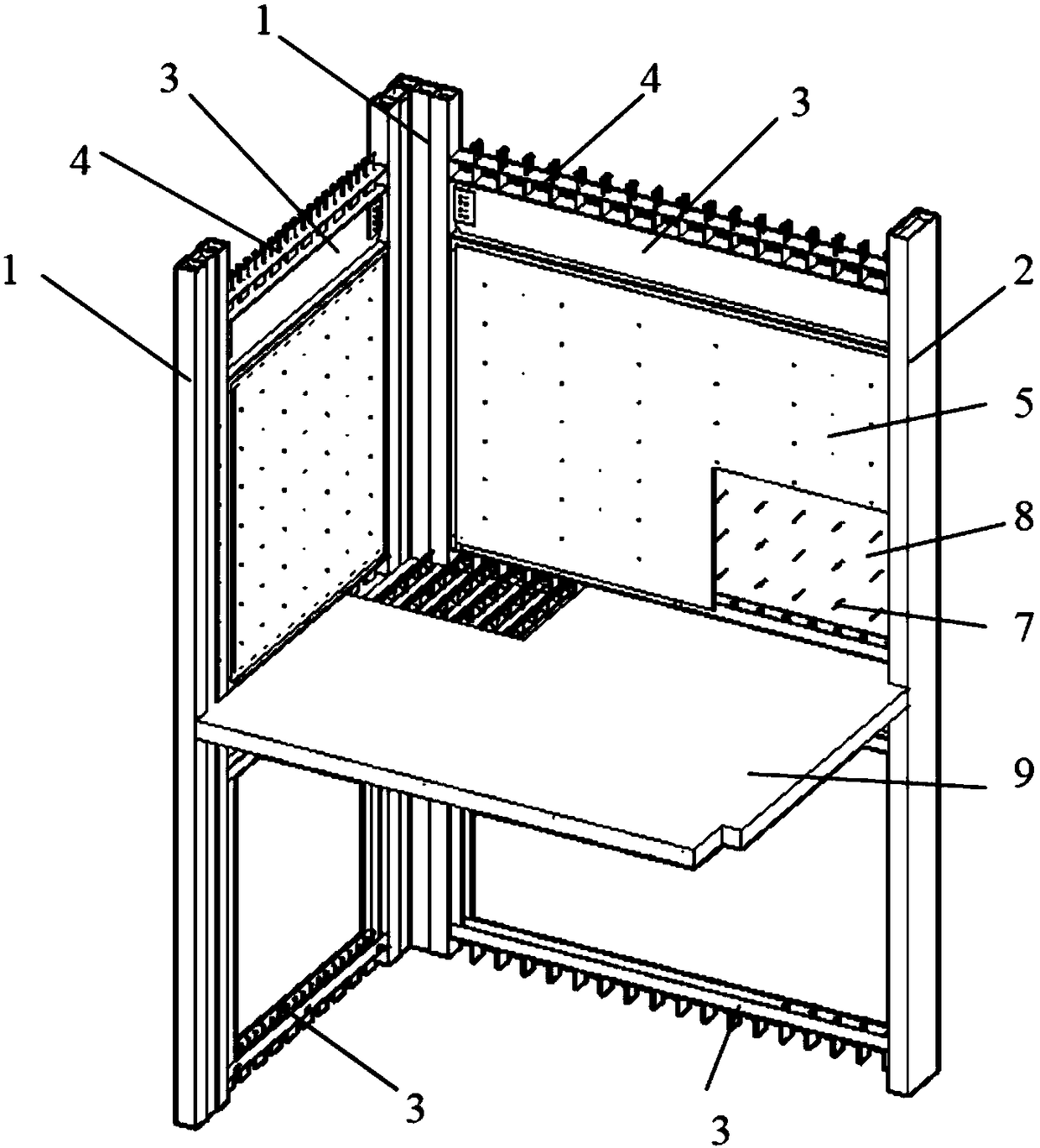
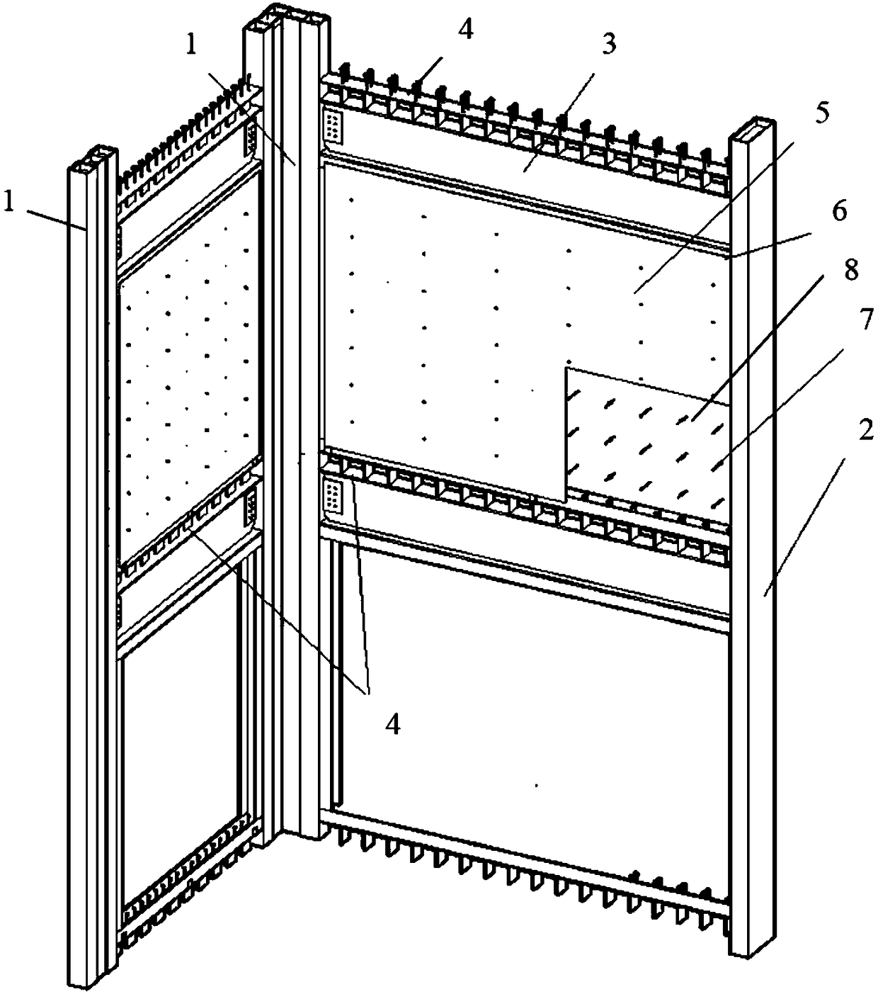
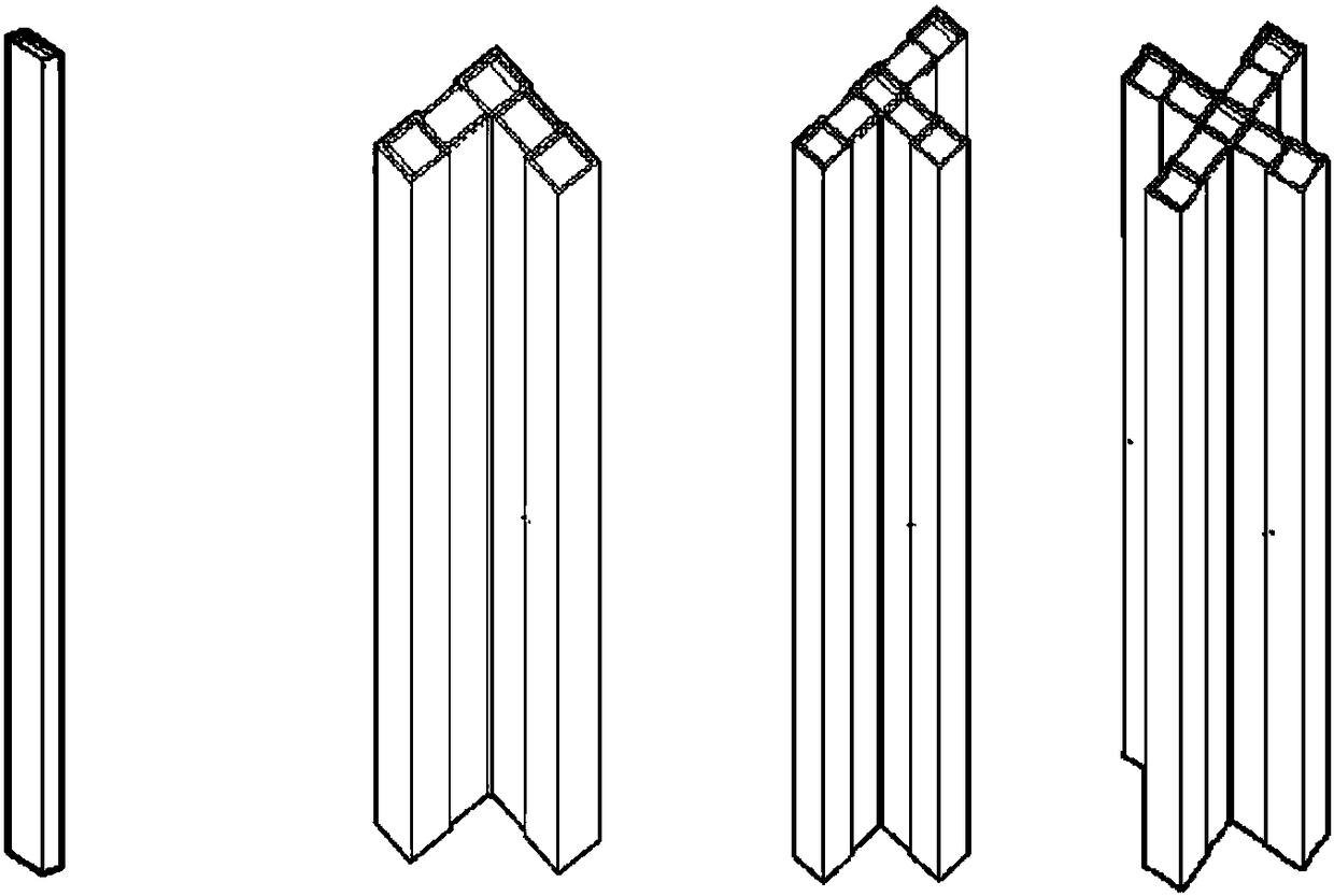
[0025] Such as Figure 1 to Figure 2 As shown, an assembled square steel pipe and steel plate concrete composite shear wall includes a vertical beam and a cross beam to form a frame structure; the vertical beam includes a special-shaped square steel pipe group 1 and a single square steel pipe 2; the cross beam inclu...


PUM


Abstract

The invention discloses an assembled shear wall formed by combining square steel pipes with steel plate concrete. The shear wall includes a frame structure formed by vertical girders and cross beams;the vertical girders include special-shaped square steel pipe groups (1) and single square steel pipes (2); the cross beams include H-shaped steel girders (3); the H-shaped steel girders (3) are welded to the special-shaped square steel pipe groups (1) or the single square steel pipes (2) to serve as interlayer cross beams; bidirectional connectors (4) above the H-shaped steel girders (3) enable the upper and lower layers to be communicated with each other; steel plates (5) are welded to the two side surfaces of a square space formed by the H-shaped steel girders (3) on the upper layer, the bidirectional connectors (4) on the lower layer and the special-shaped square steel pipe groups (1) or the single square steel pipes (2) on both sides; concrete (8) is poured between the two steel plates (5). The arrangement is flexible, the stress is clear, the lateral resistance capability of a structural system is obviously improved, a steel plate concrete combined structure and the frame structure can cooperatively work and can be compatibly deformed, two quakeproof defense lines are formed, and the quakeproof performance is reliably ensured.

Description

technical field [0001] The invention relates to the technical field of building structures, in particular to an assembled square steel tube steel plate concrete composite shear wall. Background technique [0002] At present, the structural systems often used in high-rise residential buildings include shear wall structure, frame-shear wall structure, frame support-shear wall structure, etc. Or introduce a shear wall system with stronger lateral stiffness into the super high-rise structure. Reinforced concrete shear wall is one of the most commonly used shear wall forms in structures at present. It is favored by the majority of designers for its advantages of good integrity, high rigidity, small lateral deformation, and good resistance to wind load and small and medium-level earthquakes. , but its own shortcomings are also prominent, such as excessive stiffness, low ductility, early cracks, shear damage in the later stage of stress, and difficult repair after earthquakes. In ...

Claims


Application Information

Patent Timeline
IPC IPC(8): E04B2/58
CPCE04B2/58
Inventor 赵钊陈华周陈志华宫健周婷张相勇张步亭王毅国玮琦周晓辉
Owner CHINA CONSTR STEEL STRUCTURE CORP LTD
Why Eureka
Try Eureka