Supercharge Your Innovation With Domain-Expert AI Agents!

Suspended ceiling suspending component and suspending method thereof

A technology for suspended ceilings and components, applied in ceilings, building components, buildings, etc., can solve the problems of large damage to the original concrete, prolong the construction period, and unfavorable rapid construction, so as to shorten the construction period, reduce the difficulty of installation and debugging, and facilitate installation quality effect

Pending Publication Date: 2018-05-29
ZHEJIANG YASHA DECORATION
View PDF6 Cites 0 Cited by
  • Summary
  • Abstract
  • Description
  • Claims
  • Application Information

AI Technical Summary

Problems solved by technology

The inventor found in the process of realizing the invention that the installation method of the above-mentioned suspended ceiling has the following disadvantages: first, the weight of the suspended ceiling is relatively large. Concentrated and deformed, the stability of the ceiling after installation is poor; second, the ceiling keel is located on the ceiling, once the ceiling is hung on the top surface, the position of the ceiling keel cannot be adjusted. It increases the workload and prolongs the construction period, which is not conducive to standardized and rapid construction; third, the deflection of the suspender is large, and it is necessary to open multiple holes on the original concrete on the top surface for reverse support. greater damage

Method used


Image

  • Suspended ceiling suspending component and suspending method thereof
  • Suspended ceiling suspending component and suspending method thereof
  • Suspended ceiling suspending component and suspending method thereof

Examples


Embodiment Construction

[0025] The directional terms such as up, down, left, right, front, back, front, back, top, and bottom that are mentioned or may be mentioned in this specification are defined relative to the structures shown in the drawings. The words " "Inside" and "outside" respectively refer to the direction toward or away from the geometric center of a specific component. They are relative concepts, so they may change accordingly according to their different positions and different usage states. Accordingly, these or other directional terms should not be construed as limiting terms.

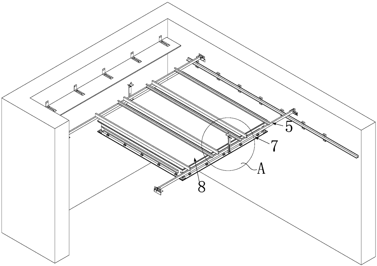
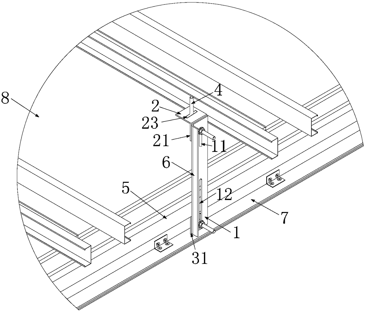
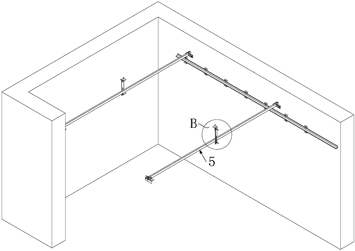
[0026] figure 1 Schematic diagram of the structure of the ceiling hook assembly provided by the optional embodiment of the present invention, figure 2 for figure 1 Partial enlarged view of A, image 3 A schematic diagram of the structure of the ceiling keel lapped on the support plate provided by the optional embodiment of the present invention, Figure 4 for image 3 Partial enlarged view of B in middl...


PUM


Abstract

The invention discloses a suspended ceiling suspending component and a suspending method thereof. The suspended ceiling suspending component comprises: a vertical frame positioned on the side of a suspended ceiling; suspended ceiling keels mounted on the vertical frame, wherein each suspended ceiling keel includes a mounting face; connection plates, with a suspending plate and support plates arranged on each connection plate, wherein both the suspending plate and the support plate are perpendicular to the connection plate, a distance between the suspending plate and the support plate is adjustable, the mounting faces are attached to the surfaces of the support plates facing the suspending plates; suspending rods, wherein the first end of each suspending rod is connected to the corresponding suspending plate, and the second end of each suspending rod is extended far away from the corresponding support plate. The suspending method of the suspended ceiling suspending component allows a suspended ceiling to be fixed to the top. The suspended ceiling suspending component and the suspending method thereof have the advantages that post-mounting stability of the suspended ceiling is improved, adjusting the position of suspended ceiling keels is facilitated, less damage is caused to original concrete of the top, the suspended ceiling can be mounted with less difficulty, construction period is shortened, and standard quick construction is benefited.

Description

technical field [0001] The invention relates to the technical field of architectural decoration, in particular to a suspended ceiling hook assembly and a hook method. Background technique [0002] The suspended ceiling plays a decorative role on the top of the interior building and is an indispensable part of interior decoration. [0003] In the prior art, the side of the ceiling facing the indoor top surface is generally provided with a ceiling keel, and the ceiling keel is hung on the top surface by a suspender rod. The inventor found in the process of realizing the invention that the installation method of the above-mentioned suspended ceiling has the following disadvantages: first, the weight of the suspended ceiling is relatively large. Concentrated and deformed, the stability of the ceiling after installation is poor; second, the ceiling keel is located on the ceiling, once the ceiling is hung on the top surface, the position of the ceiling keel cannot be adjusted. I...

Claims


Application Information

Patent Timeline
Patent Type & Authority Applications(China)
IPC IPC(8): E04B9/20E04B9/06
CPCE04B9/06E04B9/20
Inventor 余文钊周东珊钟诚步挺薛猛王瑾郑波波鄢凌云
Owner ZHEJIANG YASHA DECORATION
Features
  • R&D
  • Intellectual Property
  • Life Sciences
  • Materials
  • Tech Scout
  • Unparalleled Data Quality
  • Higher Quality Content
  • 60% Fewer Hallucinations
Learn More